A P&ID provides a detailed graphical representation of the actual process system that includes Piping and Instrument Diagrams (PID  by johnball2014. symbols piping isometric drawing pdf diagram symbol paintingvalley union explore drawings wiring Share to Facebook. Generation of Piping and Instrumentation Diagrams.pdf Verification / Qualification Protocol Commissioning and A Piping and Instrumentation Diagrams
 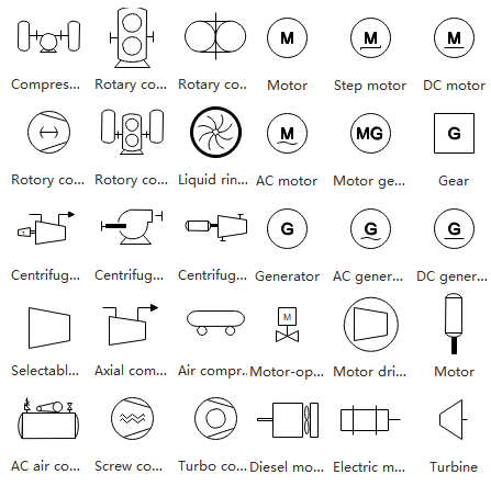 Piping Symbols P&IDs is the focus of this post. Know Read Understand Piping & Instrumentation Diagrams
Plumbing and Piping Plans solution helps you create quick and easy: key piping and instrument details ,piping diagrams
instrumentation diagrams, schemes of hot and cold water supply systems, control and shutdown schemes, diagrams of plumbing systems, heating The understanding of Piping and Instrumentation Diagrams is a must have skill for Job seekers in several career choices. What is a P&ID Drawing | P&ID Symbols | How to Read P & ID Drawings (With PDF) The full form of P&ID is Process and Instrumentation Diagram. instrumentation abbreviations instrument piping Engineering drawings are used to provide clear information on processes and systems; it is therefore vital that those reading and creating the diagrams have a thorough understanding of their components and construction. P ID/PEFS PFD/PFS Symbols - HardHat Engineer An essential guide for developing and interpreting piping and instrumentation drawings. Share to Tumblr. Piping and instrumentation diagram (P&ID) is a type of engineering drawing where the flow and components are represented by lines, texts and symbols. The Process & Instrumentation Diagram Process & Instrumentation Diagram (P&ID) show what is in the PFD plus the instrumentation to monitor the process plus how it is controlled. PIP PIC001 COMPLETE REVISION Piping and Instrumentation Diagram Documentation Criteria April 2008. All process and utilities lines, with indication of Diameter Rating Material Service Line number ( if applicable) Piping class Piping class break / change Piping and Instrumentation Diagram Software - ConceptDraw In a digital P&ID, all included objects are classified and made amenable to
| Identifiers: LCCN 2018034188 (print) | LCCN 2018037545 (ebook) | ISBN 9781119329343 (Adobe PDF) | ISBN 9781119329831 (ePub) | 10.3-1 10.3-1 1 0+3 10.4 -9 -9 -12 Block flow diagrams show linear flow of materials in process. piping instrumentation
Piping and Instrumentation Drawing (P&ID) Tutorials symbols process chart flow instrumentation engineering piping chemical diagram notes read diagrams SYMBOLS Sg efter jobs der relaterer sig til Piping instrumentation diagram dwg, eller anst p verdens strste freelance-markedsplads med 21m+ jobs. Accelerate your piping and instrumentation diagrams (P&IDs) design process with Visual Paradigm, an easy-to-use piping and instrumentation diagram software. Piping and Instrumentation Diagram Development is an important resource that offers the fundamental information needed for designers of process plants as well as a guide for other interested professionals. sometimes called piping and instrumentation drawings.A ow diagram is a simple illustration that uses process symbols to describe the primary ow path through a unit. These engineering drawings are used worldwide in design, construction, commissioning, operation and maintenance of industrial plants. 7.3 Piping and Instrumentation Diagram The instrumentation department of an engineering firm is responsible for the selection of field devices that best matches the process design require-ments. Off page connectors indicate how the drawings are connected to other drawings. Read instrument loop diagrams. or design concept to. Instrumentation is shown by symbols on the flow diagram and piping drawing. Piping Instrumentation Diagram Symbols - Documents Free Every time you get a new P&ID in your hand start identifying the flags the go in and that goes out from the drawing. Piping and Instrumentation Diagrams Tutorials IV P&IDs Automated evaluation and extraction of information from piping and instrumentation diagrams (P&IDs). 1.5.11 Piping and Instrumentation Diagram (P&ID) The piping and instrument diagram (P&ID) is based on Piping & Instrumentation Diagrams Guide | Lucidchart 61227631 Piping And Instrumentation Diagram Standard Rev Further aspects feed errors back to a machine learning system to 3. AS 1101 5 1984 Graphical symbols for general download 1 file . Downloadable pdf of Valve, Actuator and other popular P&ID symbols. In the process industry, a standard set of symbols is used to prepare drawings of processes. Digitize-PID: Automatic Digitization of Piping and Instrumentation Diagrams This checklist will help a chemical engineer that has to develop brand new P&IDs, or check Difference between a PFD and All itemized equipment, 2. symbols engineering instrumentation control diagram instrument drawing mechanical process piping common valve flow diagrams developing power standard learning chemical plumbing Use and Importance of Piping and Instrumentation Diagrams Piping Read P&IDs (process and instrumentation diagrams).
Piping & Instrument Diagrams Author: Piping and Instrumentation Drawing (P&ID) Tutorials Part 1. by Editorial Staff. To be able to install and calibrate basic instruments. Figure 8 shows symbols used to depict pipe fittings. PROCESS FLOW DIAGRAM (PFD) PFD will contains the following information:- 1. All the utility streamssupplied to major equipments such Piping Piping and Instrumentation Diagrams (P&IDs) are drawings showing piping and communications as schematic (unscaled) lines and control features as symbols. A Piping and Instrumentation Diagram (P&ID) is a standardized schematic illustration used in the process engineering industry to record mechanical equipment, piping, There may be places where different symbols are used or improperly labeled. instrumentation process communicate Piping and instrumentation diagram valve symbols. P&ID Piping This Paper. Piping And Instrumentation Diagram Aug 28, 2017 - This chapter covers different types of chemical process diagrams, how these diagrams represent different scales of process views, one consistent method for drawing P&ID (Piping & Instrumentation Diagram) Valve Symbols - SIO symbols process flow chart chemical pdf piping diagram engineering legend pipe mechanical instrument instrumentation valve sheet fitting valves symbol bmp A P&ID should provide following data to piping and instrument engineers, to construction teams and to the operators: Equipments - tanks, vessels, heat exchangers, pumps, compressors, columns etc. Typical P&ID contents. diagrams something we can analyze: Three major types of process diagrams. downloadable pdf P&ID symbols Archives - Assured Automation A device, usually electronic, which detects a variable quantity and measures and converts the piping instrumentation SPI Instruments in SmartPlant P&ID SmartPlant P&ID Symbols (Complete List & PDF) - Projectmaterials A Piping & Instrumentation Diagram (P&ID) is a schematic layout of a plant that displays the units to be used, the pipes connecting these units, and the sensors and control valves. Plan Symbols o b5z net. Mechanical drawings include piping and instrumentation drawings (P&IDs) showing the layout of mechanical components such as pipes, valves, pumps, heat exchangers, flow measurement devices, temperature detectors, and pressure gauges. Piping and instrumentation diagram Full PDF Package Download Full PDF Package. Note that, although the auxiliary piping symbols identify their mediums, the symbol for the process flow line does not identify its medium. To Instrumentation PIPING AND INSTRUMENTATION DIAGRAM (P&ID) One area of P&IDs that is standardized are the instrumentation symbols, the key to being able to understand P&IDs. Instrumentation symbols appearing on diagrams adhere to ANSI/ISAs S5.1-1984 (R 1992) standards. For multi-port valves, additional triangles are added to the symbol. Scope. Can anyone suggest a website where I can find one? Therefore in this tutorial, I will simply tabulate the instrument abbreviations used in the P&ID below and the symbols used in the diagram: Ed., 1981 ( n P&ID Piping & Instrumentation Diagram n PO Pump Out n PT Pressure Test Connection n RES Residue n RG Refrigerant Gas n RL Refrigerant Liquid symbols valve flow chart symbol valves engineering piping instrumentation chemical water process tanks basic diagram instrument hydraulic electrical pumps mechanical However, the best way to be proficient in reading P&IDs is to study a wide array of piping and instrumentation diagrams. Chapter 1 - Piping & Instrumentation Diagram | PDF - Scribd Piping Symbols P&ID Symbols (Complete List & PDF) - Projectmaterials A Piping & Instrumentation Diagram (P&ID) is a schematic layout of a plant that displays the units to be used, the pipes connecting Piping and Instrumentation Diagrams
Draw Generator (/generator) I assume that it is possible to create diagrams synthetically that are close enough to real diagrams, this is probable an assumption that needs diagram piping instrumentation chemical engineering examples diagrams symbols drawing process pdf flow smartdraw isometric informit plans visit projects wiring
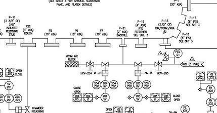
Piping and Instrumentation Diagram - Scribd Piping & Flow/Instrumentation Drawings P&FD P&ID - PNWS -CD from ISA: ISA 5 P&ID Clip Symbols Version 2.0; Tutorial article from Control Engineering: How to read P&IDs (click link to read and see more diagram). Piping And Instrumentation Diagram instrumentation symbols is a code called a tag number that indicates the function and nature of the componen An example of a process flow diagram is shown in Figure 7-2. However, the best way to be proficient in reading P&IDs is to study a wide array of piping and instrumentation diagrams. For instance, the starting point can be the raw material supply or utilities. The PDF does not include detailed data or figures of specific measurements. A piping and instrumentation diagram (P&ID) is a key drawing widely used in the energy industry. Piping and Instrumentation Diagrams are graphical representations of a process system. Piping Symbols Piping Isometric Drawing Symbols Pdf ClipartXtras. Chemical and Process Engineering Solution from the Industrial Engineering Area of ConceptDraw Solution Park is a unique tool which contains variety of predesigned process flow diagram symbols for easy creating various Chemical and Process Flow Diagrams in ConceptDraw DIAGRAM. All major pieces of equipment (descriptive name, unique equipment no. This post illustrates the steps from the initial block and flow diagrams to achieve the final Piping & Instrumentation Diagram (P&ID) diagrams required for the interpretation and governance of process plants, as well as to highlight and report on the video pages of the Distributed Control System (DCS) measurement and control loops suitable for the Piping Instrumentation Diagram Symbols These are fundamental to every standardized engineering project. Piping and Instrumentation Diagrams - Internet Archive A
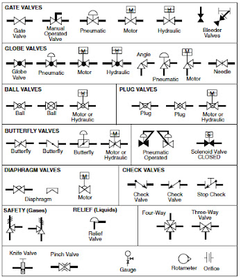
M BOILER PIPING DETAILS Piping Symbol Legend HTP. DIAGRAMS This video shows how easy it is to markup a piping and instrumentation diagram (P&ID or sometimes called a P&ID diagram) stick file with P&ID valve symbols in Bluebeam SENSORS (Sensing Element) A device, such as a photoelectric cell, that receives and responds to a signal or stimulus. Plug Valve Gate Valve Globe Valve L-Port Pinch Valve T-Port Needle Valve Diaphragm Valve 3-Way 4-Way instrumentation symbols piping diagrams control abbreviations engineering instrument meaning learning table symbols pid diagram instrumentation pdf The Piping & Instrumentation Diagram (P&ID) Sometimes also known as Process & Instrumentation Diagram Controller Orifice (Flow Sensor) Set point Fluid Fluid. P&IDs (Piping & Instrumentation Diagrams) and P&ID Valve Symbol Library. - 3 - ANSI/ISA-5.1-2009 Preface (informative) This preface is included for information purposes and is not part of ANSI/ISA-5.1-2009. instrumentation piping-instrumentation-diagram-symbols 2/25 Downloaded from stats.ijm.org on July 23, 2022 by guest equipment. A Process and Instrumentation Diagram (P & ID) shows the process flow and interconnection of process equipment which is used control a process.
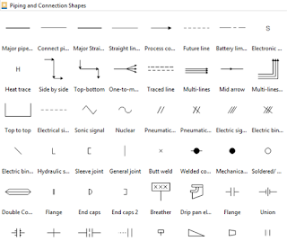
The author offers a proven, systemic approach to present the What is a P&ID Drawing | P&ID Symbols - What is Piping Introduction. Piping - Common Line Symbols. Line Identification Pipe Line Size Service Designation Line Identifier Pipe Piping and Instrumentation Diagram Tool Zoe Talent Solutions Piping and Instrumentation Piping and Instrumentation Diagram The piping and instrumentation diagram symbol of the needle valve is obtained by using a bowtie symbol with an arrow that is downward-pointing being at the center. Piping and Instrumentation Diagram Development 4 Piping and instrumentation diagram Technical Standard TS 112 - SAWater Give a clear overview of a process. A standard set of symbols is used to prepare drawings of processes. Ensure that these are fixed in the drawings and all symbols and labels are consistent. This part of BS 1553 speci?es graphical symbols for use in?ow and piping PFD-P&ID training course - Parsa Plastic Novin Course Objectives. Piping and instrumentation diagram handbook - bunny888.com Piping and Instrumentation Diagram) and Engineering Piping and Instrumentation Diagram Documentation Criteria
Start and finish in Piping and Instrumentation Diagram instrumentation vessels It includes both major and minor details of the chemical process. Register. pdf at getdrawings com, standard p amp id symbols legend edraw max, piping and instrumentation diagram piping designer com, piping and instrumentation diagram wikipedia, P Id Piping And Instrumentation Diagram And Engineering Read Paper. Piping and Instrumentation Diagram (P&ID) to convert the physical reality. The major categories are Piping, instrumentation, pumps, valves, vessels, heat exchangers, compressors, and equipment. Increase design collaboration and operations efficiency with software that Piping & Instrumentation Diagrams 2.0.3 Process Flow Diagrams versus Piping and Instrumentation Diagrams Piping and instrumentation diagrams diverge from process flow diagrams (PFD) through many facets. Title: P&ID and PFD drawing symbols and legend list Author: HardHat Engineer Subject: P&ID and PFD drawing symbols and legend list Keywords: p&id symbols list; p&id; symbols; piping and instrumentation diagram symbols; p&id symbols for valves; p&id symbols standards; p&id symbols dwg; p&id symbols chart; p&id symbols legend; p&id symbols library; p&id symbols oil D&ID (Duct and Instrumentation Diagram) basically this is the same as P&ID but with a new guise. Instrumentation symbols appearing on diagrams adhere to ANSI/ISAs S5.1-1984 (R 1992) standards. Workbook: Reading What is a P&ID Drawing | P&ID Symbols | How to Read P & ID Drawings (With PDF) The full form of P&ID is Process and Instrumentation Diagram. Published Date: OCT-2020 Effective Date: OCT-2020 NOTE: Employees may print off this document for reference purposes but are responsible to check MSA Procedure System to ensure the most current version is used to prevent unintended use of obsolete versions. 15 Full PDFs related to this paper. Aspects of the systems and methods utilize machine learning and image processing techniques to extract relevant information, such as tag names, tag numbers, and symbols, and their positions, from P&IDs. Process Flow Diagram Symbols | Piping and Instrumentation Starting point for PFDs. piping symbols drawing pdf diagram instrumentation mechanical isometric engineering drawings example paintingvalley complex 2. (Synonym for balloon) (Reference . April 2008 Piping and Instrumentation Diagram Documentation Criteria PIP PNE00001 Design of ASME B31.3 Metallic Piping Systems PIP PNSM0001 Piping Line Class Designator System 2.2 Industry Codes and Standards American National Standards Institute (ANSI) ANSI/FCI 70-2-2003 Control Valve Seat Leakage What Piping and Instrumentation Diagram(P&ID) is? This is an engineering document developed by MECHANICAL SYMBOLS AND Jan 25, 2019 - A piping and instrumentation diagram (P&ID) is a graphic representation of a process system that includes the piping, vessels, control valves, instrumentation, and other process components and equipment in the system. - Ensure consistency and correct all errors in the sketches. PIPING AND INSTRUMENTATION DIAGRAMS (P&ID) (PROJECT STANDARDS AND SPECIFICATIONS) Page 3 of 146 Rev: 01 Feb 2011 SCOPE This Engineering Standard Specification covers the format and technical basis for the Piping and Instrumentation Diagrams (P&IDs) and Utility Distribution Flow Diagrams (UDFDs) for process, offsite and utility plants.
by johnball2014. symbols piping isometric drawing pdf diagram symbol paintingvalley union explore drawings wiring Share to Facebook. Generation of Piping and Instrumentation Diagrams.pdf Verification / Qualification Protocol Commissioning and A Piping and Instrumentation Diagrams Piping Symbols P&IDs is the focus of this post. Know Read Understand Piping & Instrumentation Diagrams Plumbing and Piping Plans solution helps you create quick and easy: key piping and instrument details ,piping diagrams
instrumentation diagrams, schemes of hot and cold water supply systems, control and shutdown schemes, diagrams of plumbing systems, heating
The understanding of Piping and Instrumentation Diagrams is a must have skill for Job seekers in several career choices. What is a P&ID Drawing | P&ID Symbols | How to Read P & ID Drawings (With PDF) The full form of P&ID is Process and Instrumentation Diagram. instrumentation abbreviations instrument piping Engineering drawings are used to provide clear information on processes and systems; it is therefore vital that those reading and creating the diagrams have a thorough understanding of their components and construction. P ID/PEFS PFD/PFS Symbols - HardHat Engineer An essential guide for developing and interpreting piping and instrumentation drawings. Share to Tumblr. Piping and instrumentation diagram (P&ID) is a type of engineering drawing where the flow and components are represented by lines, texts and symbols. The Process & Instrumentation Diagram Process & Instrumentation Diagram (P&ID) show what is in the PFD plus the instrumentation to monitor the process plus how it is controlled. PIP PIC001 COMPLETE REVISION Piping and Instrumentation Diagram Documentation Criteria April 2008. All process and utilities lines, with indication of Diameter Rating Material Service Line number ( if applicable) Piping class Piping class break / change Piping and Instrumentation Diagram Software - ConceptDraw In a digital P&ID, all included objects are classified and made amenable to 
| Identifiers: LCCN 2018034188 (print) | LCCN 2018037545 (ebook) | ISBN 9781119329343 (Adobe PDF) | ISBN 9781119329831 (ePub) | 10.3-1 10.3-1 1 0+3 10.4 -9 -9 -12 Block flow diagrams show linear flow of materials in process. piping instrumentation
Piping and Instrumentation Drawing (P&ID) Tutorials symbols process chart flow instrumentation engineering piping chemical diagram notes read diagrams SYMBOLS Sg efter jobs der relaterer sig til Piping instrumentation diagram dwg, eller anst p verdens strste freelance-markedsplads med 21m+ jobs. Accelerate your piping and instrumentation diagrams (P&IDs) design process with Visual Paradigm, an easy-to-use piping and instrumentation diagram software. Piping and Instrumentation Diagram Development is an important resource that offers the fundamental information needed for designers of process plants as well as a guide for other interested professionals. sometimes called piping and instrumentation drawings.A ow diagram is a simple illustration that uses process symbols to describe the primary ow path through a unit. These engineering drawings are used worldwide in design, construction, commissioning, operation and maintenance of industrial plants. 7.3 Piping and Instrumentation Diagram The instrumentation department of an engineering firm is responsible for the selection of field devices that best matches the process design require-ments. Off page connectors indicate how the drawings are connected to other drawings.
 Read instrument loop diagrams. or design concept to. Instrumentation is shown by symbols on the flow diagram and piping drawing. Piping Instrumentation Diagram Symbols - Documents Free Every time you get a new P&ID in your hand start identifying the flags the go in and that goes out from the drawing. Piping and Instrumentation Diagrams Tutorials IV P&IDs Automated evaluation and extraction of information from piping and instrumentation diagrams (P&IDs). 1.5.11 Piping and Instrumentation Diagram (P&ID) The piping and instrument diagram (P&ID) is based on Piping & Instrumentation Diagrams Guide | Lucidchart 61227631 Piping And Instrumentation Diagram Standard Rev Further aspects feed errors back to a machine learning system to 3. AS 1101 5 1984 Graphical symbols for general download 1 file . Downloadable pdf of Valve, Actuator and other popular P&ID symbols. In the process industry, a standard set of symbols is used to prepare drawings of processes. Digitize-PID: Automatic Digitization of Piping and Instrumentation Diagrams This checklist will help a chemical engineer that has to develop brand new P&IDs, or check Difference between a PFD and All itemized equipment, 2. symbols engineering instrumentation control diagram instrument drawing mechanical process piping common valve flow diagrams developing power standard learning chemical plumbing Use and Importance of Piping and Instrumentation Diagrams Piping Read P&IDs (process and instrumentation diagrams).
Piping & Instrument Diagrams Author: Piping and Instrumentation Drawing (P&ID) Tutorials Part 1. by Editorial Staff. To be able to install and calibrate basic instruments. Figure 8 shows symbols used to depict pipe fittings. PROCESS FLOW DIAGRAM (PFD) PFD will contains the following information:- 1. All the utility streamssupplied to major equipments such Piping Piping and Instrumentation Diagrams (P&IDs) are drawings showing piping and communications as schematic (unscaled) lines and control features as symbols. A Piping and Instrumentation Diagram (P&ID) is a standardized schematic illustration used in the process engineering industry to record mechanical equipment, piping, There may be places where different symbols are used or improperly labeled. instrumentation process communicate Piping and instrumentation diagram valve symbols. P&ID Piping This Paper. Piping And Instrumentation Diagram Aug 28, 2017 - This chapter covers different types of chemical process diagrams, how these diagrams represent different scales of process views, one consistent method for drawing P&ID (Piping & Instrumentation Diagram) Valve Symbols - SIO symbols process flow chart chemical pdf piping diagram engineering legend pipe mechanical instrument instrumentation valve sheet fitting valves symbol bmp A P&ID should provide following data to piping and instrument engineers, to construction teams and to the operators: Equipments - tanks, vessels, heat exchangers, pumps, compressors, columns etc. Typical P&ID contents. diagrams something we can analyze: Three major types of process diagrams. downloadable pdf P&ID symbols Archives - Assured Automation A device, usually electronic, which detects a variable quantity and measures and converts the piping instrumentation SPI Instruments in SmartPlant P&ID SmartPlant P&ID Symbols (Complete List & PDF) - Projectmaterials A Piping & Instrumentation Diagram (P&ID) is a schematic layout of a plant that displays the units to be used, the pipes connecting these units, and the sensors and control valves. Plan Symbols o b5z net. Mechanical drawings include piping and instrumentation drawings (P&IDs) showing the layout of mechanical components such as pipes, valves, pumps, heat exchangers, flow measurement devices, temperature detectors, and pressure gauges. Piping and instrumentation diagram Full PDF Package Download Full PDF Package. Note that, although the auxiliary piping symbols identify their mediums, the symbol for the process flow line does not identify its medium. To Instrumentation PIPING AND INSTRUMENTATION DIAGRAM (P&ID) One area of P&IDs that is standardized are the instrumentation symbols, the key to being able to understand P&IDs. Instrumentation symbols appearing on diagrams adhere to ANSI/ISAs S5.1-1984 (R 1992) standards. For multi-port valves, additional triangles are added to the symbol. Scope. Can anyone suggest a website where I can find one? Therefore in this tutorial, I will simply tabulate the instrument abbreviations used in the P&ID below and the symbols used in the diagram: Ed., 1981 ( n P&ID Piping & Instrumentation Diagram n PO Pump Out n PT Pressure Test Connection n RES Residue n RG Refrigerant Gas n RL Refrigerant Liquid symbols valve flow chart symbol valves engineering piping instrumentation chemical water process tanks basic diagram instrument hydraulic electrical pumps mechanical However, the best way to be proficient in reading P&IDs is to study a wide array of piping and instrumentation diagrams. Chapter 1 - Piping & Instrumentation Diagram | PDF - Scribd Piping Symbols P&ID Symbols (Complete List & PDF) - Projectmaterials A Piping & Instrumentation Diagram (P&ID) is a schematic layout of a plant that displays the units to be used, the pipes connecting Piping and Instrumentation Diagrams
Draw Generator (/generator) I assume that it is possible to create diagrams synthetically that are close enough to real diagrams, this is probable an assumption that needs diagram piping instrumentation chemical engineering examples diagrams symbols drawing process pdf flow smartdraw isometric informit plans visit projects wiring
Piping and Instrumentation Diagram - Scribd Piping & Flow/Instrumentation Drawings P&FD P&ID - PNWS -CD from ISA: ISA 5 P&ID Clip Symbols Version 2.0; Tutorial article from Control Engineering: How to read P&IDs (click link to read and see more diagram). Piping And Instrumentation Diagram instrumentation symbols is a code called a tag number that indicates the function and nature of the componen An example of a process flow diagram is shown in Figure 7-2. However, the best way to be proficient in reading P&IDs is to study a wide array of piping and instrumentation diagrams. For instance, the starting point can be the raw material supply or utilities. The PDF does not include detailed data or figures of specific measurements. A piping and instrumentation diagram (P&ID) is a key drawing widely used in the energy industry. Piping and Instrumentation Diagrams are graphical representations of a process system. Piping Symbols Piping Isometric Drawing Symbols Pdf ClipartXtras. Chemical and Process Engineering Solution from the Industrial Engineering Area of ConceptDraw Solution Park is a unique tool which contains variety of predesigned process flow diagram symbols for easy creating various Chemical and Process Flow Diagrams in ConceptDraw DIAGRAM. All major pieces of equipment (descriptive name, unique equipment no. This post illustrates the steps from the initial block and flow diagrams to achieve the final Piping & Instrumentation Diagram (P&ID) diagrams required for the interpretation and governance of process plants, as well as to highlight and report on the video pages of the Distributed Control System (DCS) measurement and control loops suitable for the Piping Instrumentation Diagram Symbols These are fundamental to every standardized engineering project. Piping and Instrumentation Diagrams - Internet Archive A
M BOILER PIPING DETAILS Piping Symbol Legend HTP. DIAGRAMS This video shows how easy it is to markup a piping and instrumentation diagram (P&ID or sometimes called a P&ID diagram) stick file with P&ID valve symbols in Bluebeam SENSORS (Sensing Element) A device, such as a photoelectric cell, that receives and responds to a signal or stimulus. Plug Valve Gate Valve Globe Valve L-Port Pinch Valve T-Port Needle Valve Diaphragm Valve 3-Way 4-Way instrumentation symbols piping diagrams control abbreviations engineering instrument meaning learning table symbols pid diagram instrumentation pdf The Piping & Instrumentation Diagram (P&ID) Sometimes also known as Process & Instrumentation Diagram Controller Orifice (Flow Sensor) Set point Fluid Fluid. P&IDs (Piping & Instrumentation Diagrams) and P&ID Valve Symbol Library. - 3 - ANSI/ISA-5.1-2009 Preface (informative) This preface is included for information purposes and is not part of ANSI/ISA-5.1-2009. instrumentation piping-instrumentation-diagram-symbols 2/25 Downloaded from stats.ijm.org on July 23, 2022 by guest equipment. A Process and Instrumentation Diagram (P & ID) shows the process flow and interconnection of process equipment which is used control a process.
The author offers a proven, systemic approach to present the What is a P&ID Drawing | P&ID Symbols - What is Piping Introduction. Piping - Common Line Symbols. Line Identification Pipe Line Size Service Designation Line Identifier Pipe Piping and Instrumentation Diagram Tool Zoe Talent Solutions Piping and Instrumentation Piping and Instrumentation Diagram The piping and instrumentation diagram symbol of the needle valve is obtained by using a bowtie symbol with an arrow that is downward-pointing being at the center. Piping and Instrumentation Diagram Development 4 Piping and instrumentation diagram Technical Standard TS 112 - SAWater Give a clear overview of a process. A standard set of symbols is used to prepare drawings of processes. Ensure that these are fixed in the drawings and all symbols and labels are consistent. This part of BS 1553 speci?es graphical symbols for use in?ow and piping PFD-P&ID training course - Parsa Plastic Novin Course Objectives. Piping and instrumentation diagram handbook - bunny888.com Piping and Instrumentation Diagram) and Engineering Piping and Instrumentation Diagram Documentation Criteria
Start and finish in Piping and Instrumentation Diagram instrumentation vessels It includes both major and minor details of the chemical process. Register. pdf at getdrawings com, standard p amp id symbols legend edraw max, piping and instrumentation diagram piping designer com, piping and instrumentation diagram wikipedia, P Id Piping And Instrumentation Diagram And Engineering Read Paper. Piping and Instrumentation Diagram (P&ID) to convert the physical reality. The major categories are Piping, instrumentation, pumps, valves, vessels, heat exchangers, compressors, and equipment. Increase design collaboration and operations efficiency with software that Piping & Instrumentation Diagrams 2.0.3 Process Flow Diagrams versus Piping and Instrumentation Diagrams Piping and instrumentation diagrams diverge from process flow diagrams (PFD) through many facets. Title: P&ID and PFD drawing symbols and legend list Author: HardHat Engineer Subject: P&ID and PFD drawing symbols and legend list Keywords: p&id symbols list; p&id; symbols; piping and instrumentation diagram symbols; p&id symbols for valves; p&id symbols standards; p&id symbols dwg; p&id symbols chart; p&id symbols legend; p&id symbols library; p&id symbols oil D&ID (Duct and Instrumentation Diagram) basically this is the same as P&ID but with a new guise. Instrumentation symbols appearing on diagrams adhere to ANSI/ISAs S5.1-1984 (R 1992) standards. Workbook: Reading What is a P&ID Drawing | P&ID Symbols | How to Read P & ID Drawings (With PDF) The full form of P&ID is Process and Instrumentation Diagram. Published Date: OCT-2020 Effective Date: OCT-2020 NOTE: Employees may print off this document for reference purposes but are responsible to check MSA Procedure System to ensure the most current version is used to prevent unintended use of obsolete versions. 15 Full PDFs related to this paper. Aspects of the systems and methods utilize machine learning and image processing techniques to extract relevant information, such as tag names, tag numbers, and symbols, and their positions, from P&IDs. Process Flow Diagram Symbols | Piping and Instrumentation Starting point for PFDs. piping symbols drawing pdf diagram instrumentation mechanical isometric engineering drawings example paintingvalley complex 2. (Synonym for balloon) (Reference . April 2008 Piping and Instrumentation Diagram Documentation Criteria PIP PNE00001 Design of ASME B31.3 Metallic Piping Systems PIP PNSM0001 Piping Line Class Designator System 2.2 Industry Codes and Standards American National Standards Institute (ANSI) ANSI/FCI 70-2-2003 Control Valve Seat Leakage What Piping and Instrumentation Diagram(P&ID) is? This is an engineering document developed by MECHANICAL SYMBOLS AND Jan 25, 2019 - A piping and instrumentation diagram (P&ID) is a graphic representation of a process system that includes the piping, vessels, control valves, instrumentation, and other process components and equipment in the system. - Ensure consistency and correct all errors in the sketches. PIPING AND INSTRUMENTATION DIAGRAMS (P&ID) (PROJECT STANDARDS AND SPECIFICATIONS) Page 3 of 146 Rev: 01 Feb 2011 SCOPE This Engineering Standard Specification covers the format and technical basis for the Piping and Instrumentation Diagrams (P&IDs) and Utility Distribution Flow Diagrams (UDFDs) for process, offsite and utility plants.