On the shield you can control up to two Servo motors. If they do not correspond with the desired direction, you have to invert the wires to the M1 port. You now have a great way to control motor direction and speed using your Arduino. An example of this can be found in Basic_Control.ino, attached. The following sketch will give you complete understanding on how to control a unipolar or bipolar stepper motor with L293D shield and is same for both the motors except stepsPerRevolution parameter. Stack the shield on top of the Arduino board.
There are two ways to apply power to the motor: 1) You can power the Motorshield and the DC motor via the DC Barrel Jack or USB port and insert the VIN Jumper shown as the tall black handle right next to the green Power LED below. The current sense pins are A0 (Channel A) and A1 (Channel B). One of the easiest and inexpensive way to do that is to interface L293D Motor Driver Shield with Arduino. This also makes it drop-in compatible with any Arduino, such as the Uno, Leonardo, Due and Mega R3. V1 uses L293D Darlington driver and V2 has the TB6612 MOSFET driver. This can be done with the following code: To control the motors direction, Pin 12 (Channel A) and Pin 13 (Channel B) are used. We use cookies to guarantee you the best experience on our site.
my motor shield is not worked, how to fix them? HIGH HIGH LOW 1.4V 1.4V Change this parameter as per your motors specification before trying the sketch out.
You can also connect two stepper motors to output terminals.
It has the capability of controlling up to 2 stepper motors, 4 DC motors. Lets connect stepper motor to the L293D shield. eet DoRobot Assembly Techniques J3 Caterpillar-Crawler-Chassis v 1.0 ArduSerie#46, Tested compatible with Mega, Diecimila, & Duemilanove, Try soldering a ceramic or disc 0.1uF capacitor between the motor tabs (on the motor itself!) It also has much lower voltage drops across the motor so you get more torque out of your batteries, and there are built-in flyback diodes as well. Helper that sets the PWM output on a pin and manages 'all on or off'.
Mini factory that will return a pointer to an already-allocated, Adafruit_MotorShield::Adafruit_MotorShield, Optional I2C address if you've changed it. Thank you so much , this really helped me. The following sketch will give you complete understanding on how to control speed and spinning direction of a DC motor with L293D motor driver shield and can serve as the basis for more practical experiments and projects. The on-board LED indicates the motor power supply is Okay. The shield brings out the 16bit PWM output lines to two 3-pin headers to which you can connect two servo motors. Restart your Arduino IDE and check if you have a submenu called File -> Example -> AFMotor. Once you have defined the motor objects, you can define the setup() function. As a bonus, the shield offers below features: The output channels of both the L293D chips are broken out to the edge of the shield with two 5-pin screw terminals viz. At the heart of this shield is the L298P dual full bridge driver that can handle up to 3 amps for very short durations or 2 amps continuously per channel. The default address is 0x060 which is the address assigned by default to any Adafruit motorshield. For example, following code snippet creates two AFmotor objects. In the following figure you can see it in the middle of the board. Adafruit Motor Shield v1.0 (I got this one at a local store but I think it is also available on Amazon or other similar sites). Search for available I2C addresses on bus 0 to specify a different address.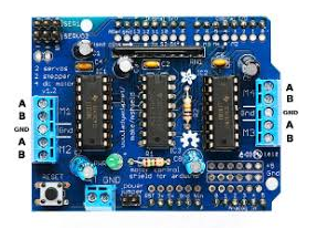 Connect to the top two terminal ports; do not connect to the middle pin (GND). Mini factory that will return a pointer to an already-allocated Adafruit_DCMotor object. Here you need to pass steps-per-revolution of motor and port number to which motor is connected, as parameters. A pointer to an optional I2C interface. 2 years ago, HelloI would like information on the H-Bridge pin connections to the Arduino for M1, M2, M3, M4, Servo 1 and Servo 2. There are four DC motor ports available on each shield. If you wish to stack the shields it is necessary that each one must have a unique I2C address. void step(uint16_t steps, uint8_t dir, uint8_t style = SINGLE); function. Create an add-on shield object by specifying the required library name parameter: The I2CAddress of a shield is set to 0x60 by default if not specified. Current sensing can be useful for robotics applications, such as traction control and determining if the robotis pushing an object. The shield also comes with a 74HC595 shift register that extends 4 digital pins of the Arduino to the 8 direction control pins of two L293D chips. This chip handles all the motor and speed controls over I2C. LOW LOW LOW 1.4V 1.4V
To interact with the Motor Shield V2, we use the library Adafruit_MotorShield.h . Start by plugging the shield on the top of the Arduino. Filter your search by typing motor shield. 5 years ago, Yeah the board works well with 12v power supply. If not provided, we use Wire or Wire1 (on Due), The DC motor port we want to use: 1 thru 4 are valid, How many steps per revolution (used for RPM calculation), The stepper motor port we want to use: only 1 or 2 are valid, The PWM output on the driver that we want to control (0-15), The 12-bit PWM value we want to set (0-4095) - 4096 is a special 'all on' value. someone please help! DO NOT supply power to the EXT_PWR input when jumper is in place. See the photo below for the red and blue wire example. DIRA BRAKEA PWMA A+ A- To drive the motor forward* this pins needs to be brought high. Start by plugging the shield on the top of the Arduino. Using the Arduino IDE, upload the code to your Arduino board. Channel B = PIN 8. Thus, when you deal with servos you do not need to use the Adafruit Motorshield library, but include directly the Servos library. Installing and Setting up Kali Linux in TermuxDevelopment with Android. The motor shield has quite a few features such as current measuring and the ability to drive a single stepper motor.
MathWorks is the leading developer of mathematical computing software for engineers and scientists. Start the motor and change the speed while it is running. In case of interest to anyone, here is a truth table of the Arduino Motor Shield Rev3, channel A. Accelerating the pace of engineering and science. But what should I do if I have more than four motors? Connect a DC toy/hobby motor to motor port 1, labeled 'M2' on the shield. An example of this can be found in Basic_Control.ino, attached. It is not compatible with the V1 library! Thorough example code is available for all the sections in the attached zipped folder. Power connects to Power terminal block. The steps parameter specifies the number of steps per revolution.
The Arduino code is used to control the board, while the Processing one is used for better visualization. Instead, regarding the n parameter, if you connect the motor to the M1 and M2 ports then you must specify 1, else if you connect the motor to the M3 and M4 ports then you must specify 2. As the shield comes with two L293D motor driver chipsets, that means it can individually drive up to four DC motors making it ideal for building four-wheel robot platforms. Get the BOM. In setup and loop section of the code we simply call below two functions to control the speed and spinning direction of a motor. HIGH or LOW depending on the value you want.
By default, the motor will hold the position after every stepping is done. The steps parameter specifies how many steps to move, the dir parameter specify the direction (FORWARD or BACKWARD) and the style parameter specifies the stepping style (SINGLE, DOUBLE, INTERLEAVED or MICROSTEP). Custom NanoLeaf Lights! Be sure to double check the polarity with a volt meter!
This site uses Akismet to reduce spam. Each channel on the module can deliver up to 600mA to the DC motor. LOW LOW HIGH 0V VMOT In our experiment we are connecting it to M4. The Adafruit Motorshield can run unipolar (5-wire and 6-wire) and bipolar (4-wire) steppers. The Arduino Motor Shield is a shield that lets you control various loads that a typical Arduino pin cannot drive. Create a DC motor object at port 2. Set the motor's RPM, e.g revolutions per minute, to 10 and move or step the motor 200 steps in one direction and then another 200 steps in the reverse direction. Digital pins #2, #13 and analog pins A0-A5 are not used by the shield. 3. To set the I2C address, you use have to use a drop of solder to bridge thecorresponding address jumper for each binary 1 in the address.
Is it necessary to remove power jumper pin while connecting external power source to the motor drive shield? The power supplied by the Arduino board is not enough, so you need to connect the motorshield as shown in the following way.
Copyright 2022 LastMinuteEngineers.com. On the Arduino board, there are two pins dedicated to the I2C protocol: A4 for the SDA (data line) and A5 for the SCL (clock line). There exists three scenarios when it comes to supplying power for the motors through shield. If you need to use several motorshields you need to assign a unique and different I2C address for each shield. The sketch starts by including the AFMotor.h library.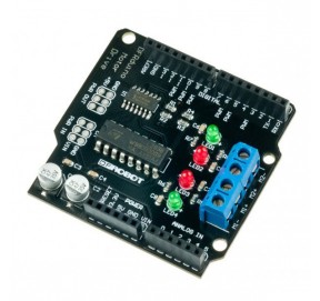 The core of this shield is the motor driver chipToshiba TB6612FNG (hereyou can find all the technical specifications). 3. http://www.pololu.com Most of the drivers are capable of more current than the basic motor shield, and using the same code. If you can't see the submenu, check the steps above. Love it! First, download the library by clicking the link below. The first thing to do is to create the Motorshield object: The Adafruit_MotorShield class represents a single motorshield and it must be declare at the beginning before using any object of the library. Connect a six-wire Portescap stepper motor to motor port 2, labeled 'M3' and 'M4' on the shield. Adafruit invests time and resources providing this open source code, please support Adafruit and open-source hardware by purchasing products from Adafruit! Instead of using a latch and the Arduinos PWM pins, they have a fully-dedicated PWM driver chip onboard. Which mean, you can operate up to 32 shieds (64 steppers or DC motors 128) with a single Arduino. Click on that entry, and then select Install. First you need to include the libraries. I think this shield would be a good start for beginners because of its versatility for its price range.
 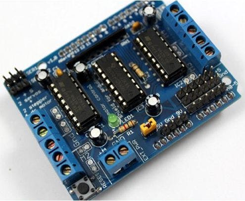 The Motor Shield V2 uses the MOSFET TB6612 with 1.2A capacity per channel and I2C communication. From a mechanical standpoint, going from forward to reverse rapidly could potentially damage a gear box. If you want to connect multiple motors to the shield, create separate object for each motor. Move the potentiometer to adjust the speed and direction of the motor. Object that controls and keeps state for the whole motor shield. You can connect four DC motors having voltages between 4.5 to 25V to these terminals. Ardu_Serie#48, DRV8825 High Current Stepper Motor Driver Carrier Stepper Motor Bipolar Mode 2.5A@45v peak Ardu_Serie #59, L298N Dual Full-Bridge Driver Darlington Transistor Arrays Based 3A@50v peak Ardu-Serie#52, TB6612FNG: Dual DC Motor Driver SparkFun Motor Driver 3.2A@13.5v peak Ardu-Serie#49, A4988 Stepper Motor Driver Carrier Allegros A4988 Bipolar Stepper Motor Driver 2A@35v peak Ardu-Serie#53, Adafruit Motor Shield v1 & v24 DC Motors or 2 Stepper Motor or 2 Servos 1.2A@25v & 3.2A@15v peak Ardu-Serie#54, IFR 520 MOS Module + DoRobot Switch Heavy DC Loads 10A@100v peak Ardu-Serie#60, L9110 H-bridge module + DoRobot DC Stepper Motor Driver Board .8A@12 v peak Ardu_Serie#62, BTS7960B- High Current PN Half Bridge High Current Motor Drive Applications NovalithIC T M 43A@24v peak ArduSerie#64, VNH2SP30 Monster Moto Shield Use This Board In Extreme High-Demand Application Full-Bridge Motor Drivers 30A@16v peak Ardu_Serie#63, J of Jungle + 3 Plats Arduino/RPi/Pic = J3. I started using Aurduino and Adrafruit Motor Shield recently. Although you can connect DC motors having voltages between 4.5 to 25V to the shield, in our experiment we are using DC Motors that are rated for 9V. Anyways thank you for checking out my instructables and I hope it will help you with your projects. The direction parameters can only assumes three values: Note that the forward and backward directions are arbitrary.
This is the library for the Adafruit Motor Shield V2 for Arduino. The Arduino board and the computer are connected through serial connection, so make sure you check the com port first. Your email address will not be published.
Differently from DC motors, the parameter passed to the setSpeed() function is the actual speed in rpm. Now, connect the motor to either M1-M2(port#1) or M3-M4(port#2) stepper motor terminals. This commit does not belong to any branch on this repository, and may belong to a fork outside of the repository. I have included two separate codes in this instructables: one is for the Arduino IDE and the other is for Processing. This type of motor has a 3-pin wire (+5V,ground, signal). The shield offers total 4 H-Bridges and each H-bridge can deliver up to 0.6A to the motor. If you want to use these pins, you can connect some headers to it. I would suggest looking at Motor Drivers at Pololu Robotics. 4. By using the Arduino Motor Shield and a potentiometer, the speed and direction of a small motor can be controlled. Kind regards. You can download it from: Note: be careful, because available on line there is the AF_Motor library which is used for v1 shields and it is not compatible with the new Motorshield v2. The brake is controlled by Pin 8 (Channel A) and Pin 9 (Channel B). It uses fewer pins than the previous version: The Motor Shield V2 has jumper to select the I2C address and is stackable. But you can easily assign an I2C address to the shield within the range [0x60-0x80] for a total of 32 unique addresses. In order to used this shield, you need to initialize several of the pins used by the shield.
Adafruit has recently made the second version of a board shield for Arduino: theAdafruit Motorshield v2 board. Create the Motor Shield object at an I2C address, default is 0x60. Hi, Guys o/ I am J3! The RESET is nothing but Arduinos reset button. To control the motors speed Pin 3 (Channel A) and Pin 11 (Channel B) can use PWM signals to vary the speed of the motors.
For motor control, it is possible to use integrated circuits directly but their use requires significant wiring can quickly become unmanageable. Our #1 Best-Selling Drone Meet the Dark Night, Have We Passed the Point of Maximum Useful Tech, Create Ubuntu Server 20.04 on Raspberry Pi 4 SD installer. Analog pins are broken out in the bottom right corner where pin 2 has a small breakout. To install the library navigate to the Sketch > Include Library > Manage Libraries Wait for Library Manager to download libraries index and update list of installed libraries. It initializes the shield for using the DC motor. So, connect external 5V power supply to the EXT_PWR terminal. LOW HIGH LOW 1.4V 1.4V In my next article I will show you how to incorporate this into a robotic platform. By using the USB connection, the current will often be limited to 500mA or 1 amp. With the attach() function you can assign to each motor the pin out to use as parameter. The speed parameter is a value between 0-255. It takes the freq parameters, which is the PWM frequency. How to use this driver shield with Stm32f108t6 Bluepill in arduino ide software, Question and 2 servos. Learn how your comment data is processed. If you attach a slip of tape as a flag, you can see the movement just described. If it is not lit, the motors will not run. The black servo is connected to the SERVO_1 slot on the board while the blue one is connected to the SERVO_2. 4. https://forum.allaboutcircuits.com/, How to Use the Arduino Joystick Shield v2.4, 4 Cell AA Holder (Or similar upto 12v) with batteries. The above code simply accelerates the DC Motor 5v forward to 10 ms and turn the motor to the reverse; Then repeat. So, connect external 12V power supply to the EXT_PWR terminal. I just make a purchase for this board after reading this and will be using your writeup for my learning. Lets see in details the four different styles of rotation. We use cookies to ensure that we give you the best experience on our website.
BSD license, check license.txt for more information. Now that we know everything about the shield, we can begin hooking it up to our Arduino! The wiper of the potentiometer goes to pin A2 and the others go to Vin (assuming you're running off of USB power) and GND. 1. In the attached zip file there is a file for the Arduino IDE titled "pot_motor_control.ino".
The L293D is a dual-channel H-Bridge motor driver capable of driving a pair of DC motors or single stepper motor. If you are using four-wire or five-wire stepper motor, check your hardware specs for appropriate connections of each wire. However, the amount of current supplied to the motor depends on systems power supply.
Amongthe wide selection of motorsthat you can use: There are many specific tutorials according to the type of motor and of their voltage. https://www.instructables.com/id/Internet-Controlled-Telepresence-Robot/.
The actual speed of the motor depends on several factors, including: sets the direction in which the motor rotates.
HIGH HIGH HIGH VMOT VMOT. Replace . with -> when function call. Its a full-featured motor shield perfect for many robot and CNC projects.
I didn't do that in the picture but I think you can figure it out on your own. The Motor Shield will output 3.3v on the current sense pins when the maximum channel current (2 amps) is reached.
There are two stepper motor ports available on each shield. Attach Adafruit motor shield to your Arduino hardware. All text above must be included in any redistribution. For this project Channel A is used. hey, is there a way to hook up two stepper motors to this shield and then control them separately using two push buttons? I have already made some design and coding and I hope it will work. You are a very good teacher.Request you to help and do your best, to upgrade people's ( uanable to go to college )knowledge .Hats off. I haven't tried on a Due board but I think more info can be found on the Adafruit website, https://learn.adafruit.com/adafruit-motor-shield/faq.
There are two ways to apply power to the motor: 1) You can power the Motorshield and the DC motor via the DC Barrel Jack or USB port and insert the VIN Jumper shown as the tall black handle right next to the green Power LED below. The current sense pins are A0 (Channel A) and A1 (Channel B). One of the easiest and inexpensive way to do that is to interface L293D Motor Driver Shield with Arduino. This also makes it drop-in compatible with any Arduino, such as the Uno, Leonardo, Due and Mega R3. V1 uses L293D Darlington driver and V2 has the TB6612 MOSFET driver. This can be done with the following code: To control the motors direction, Pin 12 (Channel A) and Pin 13 (Channel B) are used. We use cookies to guarantee you the best experience on our site.
my motor shield is not worked, how to fix them? HIGH HIGH LOW 1.4V 1.4V Change this parameter as per your motors specification before trying the sketch out.
You can also connect two stepper motors to output terminals.
It has the capability of controlling up to 2 stepper motors, 4 DC motors. Lets connect stepper motor to the L293D shield. eet DoRobot Assembly Techniques J3 Caterpillar-Crawler-Chassis v 1.0 ArduSerie#46, Tested compatible with Mega, Diecimila, & Duemilanove, Try soldering a ceramic or disc 0.1uF capacitor between the motor tabs (on the motor itself!) It also has much lower voltage drops across the motor so you get more torque out of your batteries, and there are built-in flyback diodes as well. Helper that sets the PWM output on a pin and manages 'all on or off'.
Mini factory that will return a pointer to an already-allocated, Adafruit_MotorShield::Adafruit_MotorShield, Optional I2C address if you've changed it. Thank you so much , this really helped me. The following sketch will give you complete understanding on how to control speed and spinning direction of a DC motor with L293D motor driver shield and can serve as the basis for more practical experiments and projects. The on-board LED indicates the motor power supply is Okay. The shield brings out the 16bit PWM output lines to two 3-pin headers to which you can connect two servo motors. Restart your Arduino IDE and check if you have a submenu called File -> Example -> AFMotor. Once you have defined the motor objects, you can define the setup() function. As a bonus, the shield offers below features: The output channels of both the L293D chips are broken out to the edge of the shield with two 5-pin screw terminals viz. At the heart of this shield is the L298P dual full bridge driver that can handle up to 3 amps for very short durations or 2 amps continuously per channel. The default address is 0x060 which is the address assigned by default to any Adafruit motorshield. For example, following code snippet creates two AFmotor objects. In the following figure you can see it in the middle of the board. Adafruit Motor Shield v1.0 (I got this one at a local store but I think it is also available on Amazon or other similar sites). Search for available I2C addresses on bus 0 to specify a different address.
Connect to the top two terminal ports; do not connect to the middle pin (GND). Mini factory that will return a pointer to an already-allocated Adafruit_DCMotor object. Here you need to pass steps-per-revolution of motor and port number to which motor is connected, as parameters. A pointer to an optional I2C interface. 2 years ago, HelloI would like information on the H-Bridge pin connections to the Arduino for M1, M2, M3, M4, Servo 1 and Servo 2. There are four DC motor ports available on each shield. If you wish to stack the shields it is necessary that each one must have a unique I2C address. void step(uint16_t steps, uint8_t dir, uint8_t style = SINGLE); function. Create an add-on shield object by specifying the required library name parameter: The I2CAddress of a shield is set to 0x60 by default if not specified. Current sensing can be useful for robotics applications, such as traction control and determining if the robotis pushing an object. The shield also comes with a 74HC595 shift register that extends 4 digital pins of the Arduino to the 8 direction control pins of two L293D chips. This chip handles all the motor and speed controls over I2C. LOW LOW LOW 1.4V 1.4V To interact with the Motor Shield V2, we use the library Adafruit_MotorShield.h . Start by plugging the shield on the top of the Arduino. Filter your search by typing motor shield. 5 years ago, Yeah the board works well with 12v power supply. If not provided, we use Wire or Wire1 (on Due), The DC motor port we want to use: 1 thru 4 are valid, How many steps per revolution (used for RPM calculation), The stepper motor port we want to use: only 1 or 2 are valid, The PWM output on the driver that we want to control (0-15), The 12-bit PWM value we want to set (0-4095) - 4096 is a special 'all on' value. someone please help! DO NOT supply power to the EXT_PWR input when jumper is in place. See the photo below for the red and blue wire example. DIRA BRAKEA PWMA A+ A- To drive the motor forward* this pins needs to be brought high. Start by plugging the shield on the top of the Arduino. Using the Arduino IDE, upload the code to your Arduino board. Channel B = PIN 8. Thus, when you deal with servos you do not need to use the Adafruit Motorshield library, but include directly the Servos library. Installing and Setting up Kali Linux in TermuxDevelopment with Android. The motor shield has quite a few features such as current measuring and the ability to drive a single stepper motor.
MathWorks is the leading developer of mathematical computing software for engineers and scientists. Start the motor and change the speed while it is running. In case of interest to anyone, here is a truth table of the Arduino Motor Shield Rev3, channel A.
Accelerating the pace of engineering and science. But what should I do if I have more than four motors? Connect a DC toy/hobby motor to motor port 1, labeled 'M2' on the shield. An example of this can be found in Basic_Control.ino, attached. It is not compatible with the V1 library! Thorough example code is available for all the sections in the attached zipped folder. Power connects to Power terminal block. The steps parameter specifies the number of steps per revolution. The Arduino code is used to control the board, while the Processing one is used for better visualization. Instead, regarding the n parameter, if you connect the motor to the M1 and M2 ports then you must specify 1, else if you connect the motor to the M3 and M4 ports then you must specify 2. As the shield comes with two L293D motor driver chipsets, that means it can individually drive up to four DC motors making it ideal for building four-wheel robot platforms. Get the BOM. In setup and loop section of the code we simply call below two functions to control the speed and spinning direction of a motor. HIGH or LOW depending on the value you want.
By default, the motor will hold the position after every stepping is done. The steps parameter specifies how many steps to move, the dir parameter specify the direction (FORWARD or BACKWARD) and the style parameter specifies the stepping style (SINGLE, DOUBLE, INTERLEAVED or MICROSTEP). Custom NanoLeaf Lights! Be sure to double check the polarity with a volt meter!
This site uses Akismet to reduce spam. Each channel on the module can deliver up to 600mA to the DC motor. LOW LOW HIGH 0V VMOT In our experiment we are connecting it to M4. The Adafruit Motorshield can run unipolar (5-wire and 6-wire) and bipolar (4-wire) steppers. The Arduino Motor Shield is a shield that lets you control various loads that a typical Arduino pin cannot drive. Create a DC motor object at port 2. Set the motor's RPM, e.g revolutions per minute, to 10 and move or step the motor 200 steps in one direction and then another 200 steps in the reverse direction. Digital pins #2, #13 and analog pins A0-A5 are not used by the shield. 3. To set the I2C address, you use have to use a drop of solder to bridge thecorresponding address jumper for each binary 1 in the address.
Is it necessary to remove power jumper pin while connecting external power source to the motor drive shield? The power supplied by the Arduino board is not enough, so you need to connect the motorshield as shown in the following way.
Copyright 2022 LastMinuteEngineers.com. On the Arduino board, there are two pins dedicated to the I2C protocol: A4 for the SDA (data line) and A5 for the SCL (clock line). There exists three scenarios when it comes to supplying power for the motors through shield. If you need to use several motorshields you need to assign a unique and different I2C address for each shield. The sketch starts by including the AFMotor.h library.
The core of this shield is the motor driver chipToshiba TB6612FNG (hereyou can find all the technical specifications). 3. http://www.pololu.com Most of the drivers are capable of more current than the basic motor shield, and using the same code. If you can't see the submenu, check the steps above. Love it! First, download the library by clicking the link below. The first thing to do is to create the Motorshield object: The Adafruit_MotorShield class represents a single motorshield and it must be declare at the beginning before using any object of the library. Connect a six-wire Portescap stepper motor to motor port 2, labeled 'M3' and 'M4' on the shield. Adafruit invests time and resources providing this open source code, please support Adafruit and open-source hardware by purchasing products from Adafruit! Instead of using a latch and the Arduinos PWM pins, they have a fully-dedicated PWM driver chip onboard. Which mean, you can operate up to 32 shieds (64 steppers or DC motors 128) with a single Arduino. Click on that entry, and then select Install. First you need to include the libraries. I think this shield would be a good start for beginners because of its versatility for its price range. The Motor Shield V2 uses the MOSFET TB6612 with 1.2A capacity per channel and I2C communication. From a mechanical standpoint, going from forward to reverse rapidly could potentially damage a gear box. If you want to connect multiple motors to the shield, create separate object for each motor. Move the potentiometer to adjust the speed and direction of the motor. Object that controls and keeps state for the whole motor shield. You can connect four DC motors having voltages between 4.5 to 25V to these terminals. Ardu_Serie#48, DRV8825 High Current Stepper Motor Driver Carrier Stepper Motor Bipolar Mode 2.5A@45v peak Ardu_Serie #59, L298N Dual Full-Bridge Driver Darlington Transistor Arrays Based 3A@50v peak Ardu-Serie#52, TB6612FNG: Dual DC Motor Driver SparkFun Motor Driver 3.2A@13.5v peak Ardu-Serie#49, A4988 Stepper Motor Driver Carrier Allegros A4988 Bipolar Stepper Motor Driver 2A@35v peak Ardu-Serie#53, Adafruit Motor Shield v1 & v24 DC Motors or 2 Stepper Motor or 2 Servos 1.2A@25v & 3.2A@15v peak Ardu-Serie#54, IFR 520 MOS Module + DoRobot Switch Heavy DC Loads 10A@100v peak Ardu-Serie#60, L9110 H-bridge module + DoRobot DC Stepper Motor Driver Board .8A@12 v peak Ardu_Serie#62, BTS7960B- High Current PN Half Bridge High Current Motor Drive Applications NovalithIC T M 43A@24v peak ArduSerie#64, VNH2SP30 Monster Moto Shield Use This Board In Extreme High-Demand Application Full-Bridge Motor Drivers 30A@16v peak Ardu_Serie#63, J of Jungle + 3 Plats Arduino/RPi/Pic = J3. I started using Aurduino and Adrafruit Motor Shield recently. Although you can connect DC motors having voltages between 4.5 to 25V to the shield, in our experiment we are using DC Motors that are rated for 9V. Anyways thank you for checking out my instructables and I hope it will help you with your projects. The direction parameters can only assumes three values: Note that the forward and backward directions are arbitrary. This is the library for the Adafruit Motor Shield V2 for Arduino. The Arduino board and the computer are connected through serial connection, so make sure you check the com port first. Your email address will not be published.
Differently from DC motors, the parameter passed to the setSpeed() function is the actual speed in rpm. Now, connect the motor to either M1-M2(port#1) or M3-M4(port#2) stepper motor terminals. This commit does not belong to any branch on this repository, and may belong to a fork outside of the repository. I have included two separate codes in this instructables: one is for the Arduino IDE and the other is for Processing. This type of motor has a 3-pin wire (+5V,ground, signal). The shield offers total 4 H-Bridges and each H-bridge can deliver up to 0.6A to the motor. If you want to use these pins, you can connect some headers to it. I would suggest looking at Motor Drivers at Pololu Robotics. 4. By using the Arduino Motor Shield and a potentiometer, the speed and direction of a small motor can be controlled. Kind regards. You can download it from: Note: be careful, because available on line there is the AF_Motor library which is used for v1 shields and it is not compatible with the new Motorshield v2. The brake is controlled by Pin 8 (Channel A) and Pin 9 (Channel B). It uses fewer pins than the previous version: The Motor Shield V2 has jumper to select the I2C address and is stackable. But you can easily assign an I2C address to the shield within the range [0x60-0x80] for a total of 32 unique addresses. In order to used this shield, you need to initialize several of the pins used by the shield.
Adafruit has recently made the second version of a board shield for Arduino: theAdafruit Motorshield v2 board. Create the Motor Shield object at an I2C address, default is 0x60. Hi, Guys o/ I am J3! The RESET is nothing but Arduinos reset button. To control the motors speed Pin 3 (Channel A) and Pin 11 (Channel B) can use PWM signals to vary the speed of the motors.
For motor control, it is possible to use integrated circuits directly but their use requires significant wiring can quickly become unmanageable. Our #1 Best-Selling Drone Meet the Dark Night, Have We Passed the Point of Maximum Useful Tech, Create Ubuntu Server 20.04 on Raspberry Pi 4 SD installer. Analog pins are broken out in the bottom right corner where pin 2 has a small breakout. To install the library navigate to the Sketch > Include Library > Manage Libraries Wait for Library Manager to download libraries index and update list of installed libraries. It initializes the shield for using the DC motor. So, connect external 5V power supply to the EXT_PWR terminal. LOW HIGH LOW 1.4V 1.4V In my next article I will show you how to incorporate this into a robotic platform. By using the USB connection, the current will often be limited to 500mA or 1 amp. With the attach() function you can assign to each motor the pin out to use as parameter. The speed parameter is a value between 0-255. It takes the freq parameters, which is the PWM frequency. How to use this driver shield with Stm32f108t6 Bluepill in arduino ide software, Question and 2 servos. Learn how your comment data is processed. If you attach a slip of tape as a flag, you can see the movement just described. If it is not lit, the motors will not run. The black servo is connected to the SERVO_1 slot on the board while the blue one is connected to the SERVO_2. 4. https://forum.allaboutcircuits.com/, How to Use the Arduino Joystick Shield v2.4, 4 Cell AA Holder (Or similar upto 12v) with batteries. The above code simply accelerates the DC Motor 5v forward to 10 ms and turn the motor to the reverse; Then repeat. So, connect external 12V power supply to the EXT_PWR terminal. I just make a purchase for this board after reading this and will be using your writeup for my learning. Lets see in details the four different styles of rotation. We use cookies to ensure that we give you the best experience on our website.
BSD license, check license.txt for more information. Now that we know everything about the shield, we can begin hooking it up to our Arduino! The wiper of the potentiometer goes to pin A2 and the others go to Vin (assuming you're running off of USB power) and GND. 1. In the attached zip file there is a file for the Arduino IDE titled "pot_motor_control.ino".
The L293D is a dual-channel H-Bridge motor driver capable of driving a pair of DC motors or single stepper motor. If you are using four-wire or five-wire stepper motor, check your hardware specs for appropriate connections of each wire. However, the amount of current supplied to the motor depends on systems power supply.
Amongthe wide selection of motorsthat you can use: There are many specific tutorials according to the type of motor and of their voltage. https://www.instructables.com/id/Internet-Controlled-Telepresence-Robot/.
The actual speed of the motor depends on several factors, including: sets the direction in which the motor rotates.
HIGH HIGH HIGH VMOT VMOT. Replace . with -> when function call. Its a full-featured motor shield perfect for many robot and CNC projects.
I didn't do that in the picture but I think you can figure it out on your own. The Motor Shield will output 3.3v on the current sense pins when the maximum channel current (2 amps) is reached.
There are two stepper motor ports available on each shield. Attach Adafruit motor shield to your Arduino hardware. All text above must be included in any redistribution. For this project Channel A is used. hey, is there a way to hook up two stepper motors to this shield and then control them separately using two push buttons? I have already made some design and coding and I hope it will work. You are a very good teacher.Request you to help and do your best, to upgrade people's ( uanable to go to college )knowledge .Hats off. I haven't tried on a Due board but I think more info can be found on the Adafruit website, https://learn.adafruit.com/adafruit-motor-shield/faq.