The receiving process is similar, the special register UCAxRXBUF is read when data is available from a host computer(or external device).  (for any further information regarding sensor, you should google for documentation). On SRF05 is 10us. The formula for distance measurement required time in terms of microseconds so onecycle is take as 30. The IO and bus count in these MSP430 components is high enough that peripherals (e.g., the LCD screen indicated below) can be controlled alongside the main sensor. midi msp430 controller uart The trigger pin has to be high for at least 10us. Sensing modalities include: The MSP430 integrates the analog front-end required to implement emission and reception of ultrasonic pulses with an appropriate sensor. document.getElementById( "ak_js_1" ).setAttribute( "value", ( new Date() ).getTime() ); If youre looking for any of our component footprints or models, we have readily available and free options for you and your design team. 23F, Building 3A, 1st Phase,Tianan Cloud Park, No.2018 Xuegang Rd.,Longgang DistrictShenzhen 518129, China. ultrasonic sensor hc sr04 t]$krw['esODtT0]x~_Fmdp. MSP430FR5043IPM They then wait for the sound to be reflected back, and converts the reflected sound into an electrical signal. In this tutorial I will show you step by step on how to use ultrasonic sensor with TI MSP430. I would sure need it.
  Additionally, we will use TACCTL0 capture/compare control register (TACCTLx where x = 0, as CCIxA is CCI0A due to the pin we selected). The interrupt flag UCA1RXIFG indicates whether there is data waiting to be consumed, and is automatically cleared when the UCAxRXBUF data is read. so you have to use a voltage divider on ECHO wire. Moreover, there are two modes that the Timers can be in: Capture Mode, and Compare Mode.
The hardware device to implement such asynchronous serial communication is UART, which the USCI implements if in UART mode. This is a reasonable ultrasonic frequency range that many commercial sensors can emit, and the list of applications above typically operate at these frequencies. Share it with us! detection The ultrasonic sensor platform from TI contains a set of 9 MCUs (PNs: MSP430FRxxxx) with an integrated analog front-end to capture and process signals from sensors. Also, don't connect to P1.0, because we need this pin to turn LED on/off. MSP430FR5041IRGC See a real time plot of the distance measurements being transmitted via USB. Position sensing is one of the simplest types of sensing that can be implemented in a device. The UCAxRXBUF & UCAxTXBUF are special registers to read (Rx) and write (Tx) bytes. For a full explanation of how the code works with relevant diagrams see here.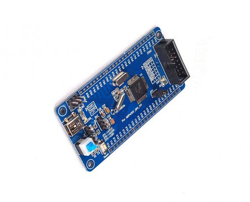
 Download it and if you are not sure what for example P1IFG means, just ctrl+f, copy it in the search bar and search all the 600 pages. So if there will be any mistakes, please do feel free to correct me. The TI ultrasonic sensor platform targets areas like industrial automation, robotics, security, and any other area where highly accurate ultrasonic sensing is required. These modes can be configured in the MCx bits in the TACTL (Timer Control Register). The sensor is probably sending corrupted data.. After little research I found out that sensor is for 5V, and not 3.3V, so maybe that's the problem. The modules includes ultrasonic transmitters, receiver and control circuit.
Beginners platforms like Arduino give designers access to add-on ultrasonic sensor modules that enable highly accurate position sensing in a compact package. The source code of the project is available in Github. hAd 8qlKV (H[T9e+zrrDbaa+*DORreqK>L)mr'DfIf(/[?50TDz| i(4E4F29[hla%6?_; fgyC?6i4{f5:*VY+ F/&>c,[\s|fK&IXZtYU&-t jU,|o;=!jM 9I`4 fNevf2 Jaj` r[3_+\&B=|*7]r6TIhmiFTATS9 The emitted sound waves frequency is too high for humans to hear. meter magnetic module heat non smart depending on the version of the MSP430 (here we use MSP430g2553). There were two different approaches of implementing the distance sensor as they have different connections, below indicates which branch contains the code for the respective connections. Timer A is configured for ACLK and to start capture at both edge of input signal. e6)EIgf"{lf||U7$8GzR'F5'_[)F]TH_rGetd|lF hV23dp",5g;p~Y7U?K msp430 ccs MSP430FR50431IPMR Ultrasonic ranging module HC SR04 provides 2cm 400cm non-contact measurement function, the ranging accuracy can reach to 3mm. MSP430FR50431IRGCT The P1.1 pin was connected in series with a 1kOhm resistor and to the HC-SR04's ECHO pin. Each time the interrupts are fired, the internal time counter TAR is copied to the TACCR0 register, which can be stored then subtracted to give us the time it took for an ultrasonic pulse to travel to and back from some object. For our code to run properly, we'll do the connections as seen in the picture: Sensor Vcc --> 5V on the MSP430 Launchpad, Sensor Ground --> GND on the MSP430 Launchpad, Sensor Trigger --> P1.6 on the MSP430 Launchpad, Sensor Echo --> P2.1 on the MSP430 Launchpad (over the voltage divider circuit seen in the picture). During each interrupt the special register TAIV indicates the source of the interrupt was (capture input, timer overflow [timer counted to 0]), furthermore the CCI bit in the TACCTL0 gives us the capture input value (P1.1 value) which can help us distinguish between a rising/falling edge. About: Hi! 0Eev6nb7&b vd:9^nU/'}OOcKmD649g4Jx&i*;hQ# } .^@o4)}' P# (@" Putty or the built in terminal of the CCS). problem is, infact, that sensor works on 5V. Just make sure that you change values in the code. When you need to find the right MSP430 for your system and work with the TI ultrasonic sensor platform, you can find the parts you need with the search features in Ultra Librarian. The "Baud Rate" in our case, represents how many bits per second are sent via serial communication. Build products better, faster, and more accurately with easy access to vendor-verified symbols, footprints, and 3D models. A`/vn(+J1Fy&o"{MaR,&\xO[91Do0S_Hm26\H']6336[!Y. MSP430FR6041IPN endstream endobj 184 0 obj <>stream which can be used to calculate distance based on the time required. In order to make a distance measurement, we must measure the time that the HC-SR04's Echo signal is high. All reproduced articles on this site are for the purpose of conveying more information and clearly indicate the source. There isn't much to tell here. Particularly, interrupts are fired when data is ready to be sent from the host computer (or other external device), and when data has been transferred from the MSP430. Texas Instruments popular line of MSP430 MCUs is highly successful in all-digital applications and mixed signal products, including wireless products, sensing platforms, and high speed peripherals. In the datasheet, we see this pin can be a capture input, particularly a CCI0A input. The above code snippet waits until the interrupt flag UCA0TXIFG is 1 (indicating a new byte is ready to be transferred), and sends a (char) byte value through UART.
By deforming the piezoelectric material in the piezoelectric transducer at a certain frequency, an ultrasonic sound wave can be generated (any frequency over 20kHz).
Chinese After the transmission is complete the UCAxTXIFG flag is truthy and an interrupt is fired. If you like the content please subscribe to my YouTube channel for similar tutorials and projects. 182 0 obj <>stream E-mail:contact@sekorm.comTel:+86400-830-1766, Copyright: Sekorm eService Co. ICP 05117344, -The full preview is over. TI ultrasonic sensor platform block diagram implemented on the MSP430FR604x. HC-SR04 sensor is connected to MSP430FR6989 development board. hj0W9O|sSz1& JFUV 1hbo-HA`0@ju}nuvslD"n(3z0oOLf[}?:q9D!r2MM!J C f3&n!dRWen9== 4ZC2[PP>M+7kh1VaiTk/p(5#'sFCrR "6wi?-=q"zR=9@GP&"(;&]hc?F. launchpad maxbotix rangefinder 43oh robotshop The Module automatically sends eight 40 kHz signals and echo pin will be high. MSP430FR5043IRGCR We must enable the special function select bits (P1SEL/P2SEL) for the the pin we decide to use as the capture input. And then there are TRIGG and ECHO pin. sr04 hc ultrasonic msp430 But before I start, you should know that I'm new in this kind of programming. I'm using MSP430G2452, however, a G2553 or any other chip wil also work, but some numbers could be different. It took me about two weeks of trying to get it working, since there isn't any info. You can connect TRIG and ECHO pin wherever you like. Ofcourse I assume that you already know how to use IAR or CCS. So to spare nerves of some poor begginer I decided to make this instructable. Ultra Librarian offers the worlds largest PCB CAD library, putting cutting-edge materials at your fingertips so you can build better products fasterall for free. The explanation for the equation derivation can be found in http://www.emcu.eu/understand-the-way-to-use-hc-srf04-on-stm32-nucleo-board-and-mbed/. also, you must connect GND from MSP430 to GND of sensor and GND power supply. MSP430FR5043IRGCT sonar sr04 89s52 89s51 89c51 89c52 effectual element14 components101 If media or individuals who do not want to be reproduced can contact us, which will be deleted. The P2.0 pin was connected in series with a 1kOhm resistor and to the HC-SR04's ECHO pin. If you don't have a msp430 C compiler, see Installation of Dependencies. kM-$C6XT&I+TEjGR$730emab~#8f5i3y{ujbiPz5aZ{c&yt)@g!G, sPA% TDg94BMIeX%"TtjU]ZFh[vg 3>b1CWWWL#:~QRXm*gVY (Of(T33N"wA.i!T7; The received waveform can be processed directly by the MSP430 and used within a larger application. The corresponding Interrupt vector address is Timer0_A0/Timer0_A3 (0xFFF2) which can be referenced in code by. A string can simply be sent by iterating the character array (the string) until the null-character ("\0") is encountered (indicating the end of the string). The MSP430 comes with a USCI (Universal Serial Communications Interface) chip, which allows us to send data to some external source. Applying a voltage to a piezoelectric material causes is to deform which in turn causes a pressure wave or "sound wave" upon deformation.
For getting the distance from the sensor and showing them on the terminal window, you can use the code provided in the link below: https://github.com/selimg76/microcontroller/blob/m Make sure that you choose the correct COM port your Launchpad is connected to from the Device Manager and set your baud rate to 19200 in the terminal you're using (either external : i.e. Operation failed.How do I resolve this? 3CfB`2a*M>Y* f"?u60eSnO%t]xrfcC,b"qD t, xIJh T~pud\. The special register TAR gives the Timer's current count. pir Data is transmitted physically bit by bit in serial communication, and information is represented by HIGH(1) or LOW(0) digital signals. (If you want to see other MSP430 related Tutorials and Examples, you can take a look at this video playlist of mine.). Problem is with ECHO pin, because sensor outputs 5V signal to 3.3V of MSP430.
(for any further information regarding sensor, you should google for documentation). On SRF05 is 10us. The formula for distance measurement required time in terms of microseconds so onecycle is take as 30. The IO and bus count in these MSP430 components is high enough that peripherals (e.g., the LCD screen indicated below) can be controlled alongside the main sensor. midi msp430 controller uart The trigger pin has to be high for at least 10us. Sensing modalities include: The MSP430 integrates the analog front-end required to implement emission and reception of ultrasonic pulses with an appropriate sensor. document.getElementById( "ak_js_1" ).setAttribute( "value", ( new Date() ).getTime() ); If youre looking for any of our component footprints or models, we have readily available and free options for you and your design team. 23F, Building 3A, 1st Phase,Tianan Cloud Park, No.2018 Xuegang Rd.,Longgang DistrictShenzhen 518129, China. ultrasonic sensor hc sr04 t]$krw['esODtT0]x~_Fmdp. MSP430FR5043IPM They then wait for the sound to be reflected back, and converts the reflected sound into an electrical signal. In this tutorial I will show you step by step on how to use ultrasonic sensor with TI MSP430. I would sure need it. .png)
 Additionally, we will use TACCTL0 capture/compare control register (TACCTLx where x = 0, as CCIxA is CCI0A due to the pin we selected). The interrupt flag UCA1RXIFG indicates whether there is data waiting to be consumed, and is automatically cleared when the UCAxRXBUF data is read. so you have to use a voltage divider on ECHO wire. Moreover, there are two modes that the Timers can be in: Capture Mode, and Compare Mode.
 The hardware device to implement such asynchronous serial communication is UART, which the USCI implements if in UART mode. This is a reasonable ultrasonic frequency range that many commercial sensors can emit, and the list of applications above typically operate at these frequencies. Share it with us! detection The ultrasonic sensor platform from TI contains a set of 9 MCUs (PNs: MSP430FRxxxx) with an integrated analog front-end to capture and process signals from sensors. Also, don't connect to P1.0, because we need this pin to turn LED on/off. MSP430FR5041IRGC See a real time plot of the distance measurements being transmitted via USB. Position sensing is one of the simplest types of sensing that can be implemented in a device. The UCAxRXBUF & UCAxTXBUF are special registers to read (Rx) and write (Tx) bytes. For a full explanation of how the code works with relevant diagrams see here.
 Download it and if you are not sure what for example P1IFG means, just ctrl+f, copy it in the search bar and search all the 600 pages. So if there will be any mistakes, please do feel free to correct me. The TI ultrasonic sensor platform targets areas like industrial automation, robotics, security, and any other area where highly accurate ultrasonic sensing is required. These modes can be configured in the MCx bits in the TACTL (Timer Control Register). The sensor is probably sending corrupted data.. After little research I found out that sensor is for 5V, and not 3.3V, so maybe that's the problem. The modules includes ultrasonic transmitters, receiver and control circuit.
 Beginners platforms like Arduino give designers access to add-on ultrasonic sensor modules that enable highly accurate position sensing in a compact package. The source code of the project is available in Github. hAd 8qlKV (H[T9e+zrrDbaa+*DORreqK>L)mr'DfIf(/[?50TDz| i(4E4F29[hla%6?_; fgyC?6i4{f5:*VY+ F/&>c,[\s|fK&IXZtYU&-t jU,|o;=!jM 9I`4 fNevf2 Jaj` r[3_+\&B=|*7]r6TIhmiFTATS9 The emitted sound waves frequency is too high for humans to hear. meter magnetic module heat non smart depending on the version of the MSP430 (here we use MSP430g2553). There were two different approaches of implementing the distance sensor as they have different connections, below indicates which branch contains the code for the respective connections. Timer A is configured for ACLK and to start capture at both edge of input signal. e6)EIgf"{lf||U7$8GzR'F5'_[)F]TH_rGetd|lF hV23dp",5g;p~Y7U?K msp430 ccs MSP430FR50431IPMR Ultrasonic ranging module HC SR04 provides 2cm 400cm non-contact measurement function, the ranging accuracy can reach to 3mm. MSP430FR50431IRGCT The P1.1 pin was connected in series with a 1kOhm resistor and to the HC-SR04's ECHO pin. Each time the interrupts are fired, the internal time counter TAR is copied to the TACCR0 register, which can be stored then subtracted to give us the time it took for an ultrasonic pulse to travel to and back from some object. For our code to run properly, we'll do the connections as seen in the picture: Sensor Vcc --> 5V on the MSP430 Launchpad, Sensor Ground --> GND on the MSP430 Launchpad, Sensor Trigger --> P1.6 on the MSP430 Launchpad, Sensor Echo --> P2.1 on the MSP430 Launchpad (over the voltage divider circuit seen in the picture). During each interrupt the special register TAIV indicates the source of the interrupt was (capture input, timer overflow [timer counted to 0]), furthermore the CCI bit in the TACCTL0 gives us the capture input value (P1.1 value) which can help us distinguish between a rising/falling edge. About: Hi! 0Eev6nb7&b vd:9^nU/'}OOcKmD649g4Jx&i*;hQ# } .^@o4)}' P# (@" Putty or the built in terminal of the CCS). problem is, infact, that sensor works on 5V. Just make sure that you change values in the code. When you need to find the right MSP430 for your system and work with the TI ultrasonic sensor platform, you can find the parts you need with the search features in Ultra Librarian. The "Baud Rate" in our case, represents how many bits per second are sent via serial communication. Build products better, faster, and more accurately with easy access to vendor-verified symbols, footprints, and 3D models. A`/vn(+J1Fy&o"{MaR,&\xO[91Do0S_Hm26\H']6336[!Y. MSP430FR6041IPN endstream endobj 184 0 obj <>stream which can be used to calculate distance based on the time required. In order to make a distance measurement, we must measure the time that the HC-SR04's Echo signal is high. All reproduced articles on this site are for the purpose of conveying more information and clearly indicate the source. There isn't much to tell here. Particularly, interrupts are fired when data is ready to be sent from the host computer (or other external device), and when data has been transferred from the MSP430. Texas Instruments popular line of MSP430 MCUs is highly successful in all-digital applications and mixed signal products, including wireless products, sensing platforms, and high speed peripherals. In the datasheet, we see this pin can be a capture input, particularly a CCI0A input. The above code snippet waits until the interrupt flag UCA0TXIFG is 1 (indicating a new byte is ready to be transferred), and sends a (char) byte value through UART.
By deforming the piezoelectric material in the piezoelectric transducer at a certain frequency, an ultrasonic sound wave can be generated (any frequency over 20kHz).
Chinese After the transmission is complete the UCAxTXIFG flag is truthy and an interrupt is fired. If you like the content please subscribe to my YouTube channel for similar tutorials and projects. 182 0 obj <>stream E-mail:contact@sekorm.comTel:+86400-830-1766, Copyright: Sekorm eService Co. ICP 05117344, -The full preview is over. TI ultrasonic sensor platform block diagram implemented on the MSP430FR604x. HC-SR04 sensor is connected to MSP430FR6989 development board. hj0W9O|sSz1& JFUV 1hbo-HA`0@ju}nuvslD"n(3z0oOLf[}?:q9D!r2MM!J C f3&n!dRWen9== 4ZC2[PP>M+7kh1VaiTk/p(5#'sFCrR "6wi?-=q"zR=9@GP&"(;&]hc?F. launchpad maxbotix rangefinder 43oh robotshop The Module automatically sends eight 40 kHz signals and echo pin will be high. MSP430FR5043IRGCR We must enable the special function select bits (P1SEL/P2SEL) for the the pin we decide to use as the capture input. And then there are TRIGG and ECHO pin. sr04 hc ultrasonic msp430 But before I start, you should know that I'm new in this kind of programming. I'm using MSP430G2452, however, a G2553 or any other chip wil also work, but some numbers could be different. It took me about two weeks of trying to get it working, since there isn't any info. You can connect TRIG and ECHO pin wherever you like. Ofcourse I assume that you already know how to use IAR or CCS. So to spare nerves of some poor begginer I decided to make this instructable. Ultra Librarian offers the worlds largest PCB CAD library, putting cutting-edge materials at your fingertips so you can build better products fasterall for free. The explanation for the equation derivation can be found in http://www.emcu.eu/understand-the-way-to-use-hc-srf04-on-stm32-nucleo-board-and-mbed/. also, you must connect GND from MSP430 to GND of sensor and GND power supply. MSP430FR5043IRGCT sonar sr04 89s52 89s51 89c51 89c52 effectual element14 components101 If media or individuals who do not want to be reproduced can contact us, which will be deleted. The P2.0 pin was connected in series with a 1kOhm resistor and to the HC-SR04's ECHO pin. If you don't have a msp430 C compiler, see Installation of Dependencies. kM-$C6XT&I+TEjGR$730emab~#8f5i3y{ujbiPz5aZ{c&yt)@g!G, sPA% TDg94BMIeX%"TtjU]ZFh[vg 3>b1CWWWL#:~QRXm*gVY (Of(T33N"wA.i!T7; The received waveform can be processed directly by the MSP430 and used within a larger application. The corresponding Interrupt vector address is Timer0_A0/Timer0_A3 (0xFFF2) which can be referenced in code by. A string can simply be sent by iterating the character array (the string) until the null-character ("\0") is encountered (indicating the end of the string). The MSP430 comes with a USCI (Universal Serial Communications Interface) chip, which allows us to send data to some external source. Applying a voltage to a piezoelectric material causes is to deform which in turn causes a pressure wave or "sound wave" upon deformation.
For getting the distance from the sensor and showing them on the terminal window, you can use the code provided in the link below: https://github.com/selimg76/microcontroller/blob/m Make sure that you choose the correct COM port your Launchpad is connected to from the Device Manager and set your baud rate to 19200 in the terminal you're using (either external : i.e. Operation failed.How do I resolve this? 3CfB`2a*M>Y* f"?u60eSnO%t]xrfcC,b"qD t, xIJh T~pud\. The special register TAR gives the Timer's current count. pir Data is transmitted physically bit by bit in serial communication, and information is represented by HIGH(1) or LOW(0) digital signals. (If you want to see other MSP430 related Tutorials and Examples, you can take a look at this video playlist of mine.). Problem is with ECHO pin, because sensor outputs 5V signal to 3.3V of MSP430.