For the ultimate limit state only, the moments derived from elastic analysis may be redistributed (up to a maximum of 30%) provided that the resulting distribution of moments remains in equilibrium with the applied loads and subject to certain limits and design criteria (e.g. Flexural Design of Reinforced Concrete Beams, Serviceability of Reinforced Concrete Beams, Shear Design of Reinforced Concrete Beams, Solution of Maximum Uniformly Distributed Service Live Load That A Beam Can Support Based on Its Flexural Strength, Types of Foundations From Construction Point of View, What are beam bridges?
Multiply shear reinforcement area by number of stirrup legs to calculate shear reinforcement area.
The reinforcement ratio shall be less than maximum reinforcement ratio and greater than minimum reinforcement ratio. Thanks for the explanation. t. Canadian Standard Association (CSA) provides similar table except for one end continuous which is l/18.
Types and Structural elements of a beam bridge, American Standard Channels Section Properties and Dimensions in Imperial Units.
The minimum reinforcement ratio in ACI code isrmin= 200/fy(psi). Typical load distribution from slab to beam is shown in the figure above.
beam calculator ws ipad app Clause 5.3.2.1 of EN 1992-1-1:2004 covers the effective flange width of beams for all limit states. The amount may be estimated from equilibrium between the tensile force in section just before cracking and the tensile force in reinforcement at yielding or at a lower stress if necessary to limit the crack width.
Please enter your email address. These slabs are typically supported by walls, reinforced concrete beams cast monolithically with the slab, steel beams (either columns or ground-supported), or a combination of all three. Load Calculation of Building.
For members with shear reinforcement the additional tensile force, Ftd, should be calculated according to clause 6.2.3 (7). beam strength stress calculator steel beams structural calculations normal height calculate stresses flange parameter cm parameters input per info
The live load of the building has to be calculated according to IS- 875 1987 part 2. Slabs distribute load uniformly on the ground and support heavy loads. beam tapered bending deflection snap stress equation calculator load construction concrete formula civil technology
In this article reinforced concret beam design is described in detail with solved examples.
For values of b/bw < 3, the basic ratios for rectangular sections should be multiplied by (11 b/bw)/10.
cesdb software structural analysis A continuous beam in a residential building is loaded as shown below. Join TheConstructor to ask questions, answer questions, write articles, and connect with other people. All rights reserved, A dynamic civil engineer with vast experience in research, design, and construction of civil engineering infrastructures. You have entered an incorrect email address!
If you use these blocks for construction, the wall loads per running meter can be as low as 5.20 kN/meter. In deep beams or beams subjected to torsion, sidebars can be used to enhance the torsion capacity and also prevent cracking. When you join you get additional benefits.
beam structural put results place before bearing load How to Create Surface Profile and Profile View in Civil 3D | AutoCAD Civil Compressive Strength of Concrete | Cube Test The Civil Engineering. 
Types of Foundation for Buildings and their Uses [PDF], Compressive Strength of Concrete -Cube Test [PDF], Procedure, Results, 16 Types of Heavy Equipment Used in Construction, Methods of Rainwater Harvesting [PDF]: Components, Transport, and Storage, Calculate Quantities of Materials for Concrete -Cement, Sand, Aggregates, 15 Factors Affecting the Selection of Construction Materials, Factors Affecting Construction Cost of a Project. The flange width for T-beams and L-beams can be derived as shown below. = 0.5sin-1 [(VRd,max/bwd))/(0.153fck (1 fck/250)] - (12)If is greater than 45, select another section.Minimum shear reinforcementAsw/S = w,min bw sin ( = 90 for vertical links)w,min = (0.08 fck)/fyk - (13). Design of Rectangular Reinforced Concrete Beam, Design of rectangular reinforced concrete beam procedure, The First approach will be presented below, Reinforcement Detailing in Beams According to IS 456-2000, Advantages of Critical Path Method (CPM) in Construction Project. 
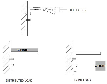
Adding the dead load of all structural components allows us to determine the total dead load of a building. These loads may be tension or compression loads.  Excessive deflection of beams can cause damages and cracking to partitions and finishes.
Can you show us how to calculate it .?
By equilibrium, the tensile force is equal to the compression resultant.
The steps in the design of a reinforced concrete beam are as follows; (a) Preliminary sizing of members(b) Estimation of design load and actions(c) Structural analysis of the beam (d) Selection of concrete cover(e) Flexural design (bending moment resistance)(f) Curtailment and anchorage(g) Shear design(h) Check for deflection(i) Check for cracking(j) Provide detailing sketches.
On the other hand, when the amount of steel is too small, the beam will fail when concrete reaches its tensile strength. A beam should not deflect excessively under service load. Beams in a reinforced concrete building can also be described in terms of their support condition such as simply supported, cantilever beams, or continuous beams.
Thanks for the comments please visit more articles by clicking on All Posts tab of the Menu Bar, you please place my backlink also and i will place your backlink, could u please read this article this is not matched with your article and i already removed those articles whose are matched with your content, this article is not matching with your content first read it carefully.
The beam is an L-beam with effective flange width of 895 mm.
Now, if we consider the load due to floor finishing to be 1 kN per meter, the superimposed live load to be 2 kN per meter, and wind load as per IS 875 to be about 2 kN per meter. Early builders of homes and buildings used beams made of wood to support the structure, but now they are made up of aluminum, steel, or other such materials.
Slabs provide flat surfaces in buildings, bridges, and other structures. Sufficient reinforcement should be provided at all sections to resist the envelope of the acting tensile force, including the effect of inclined cracks in webs and flanges. For deemed to satisfy basic span/effective depth (limiting to depth/250);Actual L/d must be Limiting L/d sThe limiting basic span/ effective depth ratio is given by;L/d = K [11 + 1.5(fck)0/ + 3.2(fck) (0/ 1)1.5] if 0 - (14)L/d = K [11 + 1.5(fck) 0/( ) + 1/12 (fck) (0/)0.5 ] if > 0 (15)Where;L/d is the limiting span/depth ratioK = Factor to take into account different structural systems0 = reference reinforcement ratio = 10-3 (fck) = Tension reinforcement ratio to resist moment due to design load = Compression reinforcement ratio. The imposed or live loads on a building are the dynamic forces or load due to the use or occupancy of the building, including furniture. In typical reinforced concrete buildings, floor beams can be categorised into; T-beams and L-beams are generally referred to as flanged beams.
Thats equal to 10 kN.
For a simply supported beam, tension is at the bottom of the beam while for a cantilever end, tension is at the top of the beam.
Or. Linear elastic analysis (with or without redistribution) or plastic can be carried depending on the one suitable for the problem. If crack control is required, a minimum amount of bonded reinforcement is required to control cracking in areas where tension is expected.
Whereb1= 0.85 for 4000 psi (30 Mpa) concrete, and reduce 0.05 for each 1000 psi of fcin excess of 4000 psi. And according to the spans with positive moments do we assume it T-shape? According to clause 7.3.1 of EN 1992-1-1:2004, cracking is normal in reinforced concrete structures subject to bending, shear, torsion or tension resulting from either direct loading or restraint or imposed deformations. In our model, we assume each meter of the beam is 350 mm wide and 650 mm high excluding slab thickness. Use 6 stirrups at 10.75 inch spacing, with first stirrup at 5".
How to Calculate Load on Column, Beam, Slab & Wall, Load Calculation on Column, Beam, Wall & Slab, When a compression member is inclined or horizontal and experiences loads, it is called a strut.
Struts are commonly used in trusses. Beams are a structural element that fights against bending.
Steel weight (1%) in Concrete = 1.125 x 0.01 x 7850 = 88.31 kg. Sorry, you do not have permission to ask a question, You must log in to ask a question. Welcome to my blog.
Forthly, find spacing for the stirrup for vertical and inclined stirrups respectively using equation 12 and 13.
When concrete reaches its maximum strain at the same time as the steel reach is yielding stress, it is called a balance condition. Beam design is described more in detail in these articles:Flexural Design of Reinforced Concrete Beams,Serviceability of Reinforced Concrete Beams, andShear Design of Reinforced Concrete Beams.
To ensure a ductile failure of the beam, ACI code limits the maximum reinforcement ratio to 0.75rb. It can offer protection against burglary and insect infestation. Let us assume that the slab has a thickness of 150 mm.Load Calculation of Building, So, each square meter of the slab would have a self-weight of.
For professional structural design practice, we should use advanced structural design software like STAAD Pro or ETABS. HT;o0w>:. Therefore, the total compressive stress in a rectangular beam is. Limits are suggested in the code but these are for general guidance only; it remains the responsibility of the designer to check whether these are appropriate for the particular case considered or whether some other limits should be used. The bending moment and shear force diagram due to the applied load is shown below; Effective depth (d) = 450 35 16/2 8 = 399mmBeff = 895mmk = MEd/(fckbeff d2) = (36.66 106)/(25 895 3992) = 0.01029, Since k < 0.167 No compression reinforcement required, z = d[0.5 + (0.25 0.882K)] z = d[0.5 + (0.25 0.882(0.01029))] = 0.95d, As1 = MEd/(0.87fyk z) = (36.66 106)/(0.87 460 0.95 399) = 241.667 mm2, The minimum area of steel required;fctm = 0.3 fck23 = 0.3 2523 = 2.5649 N/mm2 (Table 3.1 EC2). What are the different types of handrails used in bridges? The use of slabs as floor or roof structures is common in buildings.
A pedestal is a compression member whose effective length is less than three times its least lateral dimension. ACI code requirements for shear reinforcement: When shear stress, vufvc,no shear reinforcement is required. The geometry is commonly idealised by considering the structure to be made up of linear elements and plane two-dimensional elements. Hi! In addition to this, columns also perform several other functions: Enclosing buildings into different compartments allows for privacy. For calculation purpose, a stress block of 0.85fc spread over a depth, a, is used. So we have something like a transfer beam.
However, finite element analysis will use a numerical approach to transfer loads from the slab to the beam. One is when the reinforcing steel reaches its yield stress, fy.
However, deflection criteria can be used as a starting point in the analysis, even though experience is the best. What is an Arch | Components of Arch | Parts of Arch, How to Load Calculation on Column, Beam, Wall & Slab, Fill/Backfill Compaction Requirements for Sub Base, Base Course, Asphalt, What Is Tie Beam | Tie Beam Details | Advantages of Using Tie Beam, Method Statement for Plaster Works | Cement Plastering Work Procedure, Bar Bending Schedule for RCC Box Culvert in Excel | Download Sheet, General Notes for Civil Engineering | Standard Data for Civil Engineers, Types of Failure in RCC Column | Buckling, Compression, Shear, https://thecivilengineerings.com/about-me/, How to Calculate Quantity of Concrete Volume for Staircase, Dog Legged Staircase, Components & Design of Dog Legged Stair, Curing Concrete How Long it Takes & How To Cure, Thumb Rules Formula for Civil Engineers & Quantity Surveyors. The minimum cover to ensure adequate bond should not be less than the bar diameter, or equivalent bar diameter for bundled bars, unless the aggregate size is over 32 mm. We recommend moving this block and the preceding CSS link to the HEAD of your HTML file. In addition to this above loading, the columns are also subjected to bending moments that have to be considered in the final design. For flanged sections with b/bw 3, the basic ratios for rectangular sections should be multiplied by 0.8.
The depth (d), width (b), and disposition of reinforcements define the load-carrying capacity of a beam and forms the essence of their design. The design concept is simple transfer the column reactions as a concentrated load to the beams, analyse, and design accordingly.
At ultimate stress situation, the concrete at top portion is subjected to compression. We need to keep in mind some basic assumptions when designing structures. Save my name, email, and website in this browser for the next time I comment. The shear strength multiply by a reduction factor,f, needs to be larger than Vs.
Bridges and other large structures have foundations that are often made of pre-stressed concrete beams. The width of the block walls can also constraint the width of the beam. Therefore. However, for beams of equal span and uniform loading, coefficients for bending moment and shear can be obtained from Chapter 12 of Reynolds and Steedman (2005). Beams.
p(8IFN& dF RZ`aq6(8X'}` l endstream endobj 2488 0 obj 919 endobj 2448 0 obj << /Type /Page /Parent 2441 0 R /Resources << /ColorSpace << /CS2 2459 0 R /CS3 2458 0 R >> /ExtGState << /GS2 2478 0 R /GS3 2480 0 R >> /Font << /TT4 2454 0 R /TT5 2452 0 R /C2_1 2456 0 R /TT6 2450 0 R /TT7 2457 0 R >> /ProcSet [ /PDF /Text ] >> /Contents [ 2462 0 R 2464 0 R 2466 0 R 2468 0 R 2470 0 R 2472 0 R 2474 0 R 2476 0 R ] /MediaBox [ 0 0 612 792 ] /CropBox [ 0 0 612 792 ] /Rotate 0 /StructParents 0 >> endobj 2449 0 obj << /Filter /FlateDecode /Length 339 >> stream
beam structural calculations padstone steel bearing concrete foundation chimney breast frame brickwork standards eurocodes designed british height For example, if we are building a structure where the basement is being reserved for Car packing , we need much space and then we limit the number of columns. The effective width of the flange should be based on the distance lo between points of zero moment, which is shown in Figure 3.
What is the tolerance for compression test results of concrete, according to the standards?
Different methods can be used for the elastic analysis of statically indeterminate beams such as; Some coefficients are also provided in the code of practice for the evaluation of the bending moment and shear force in continuous beams. In the manual analysis of floor beams, loads are transferred from slab to beams based on the yield line assumption. Can you identify the cause of failure of this building? Keep up the good work.
An adequate concrete cover should be provided in reinforced concrete beams for the following reasons; safe transmission of bond forces durability fire resistance. These transfer the load from the superstructure to the foundation. After that, find reinforcement ratio corresponding to the computed flexural resistance compute above. beam involves the selection of the proper beam size and area of reinforcement to carry the applied load without failing or deflecting excessively.
In EC2, the concrete resistance shear stress without shear reinforcement is given by; VRd,c = [CRd,c k(1001 fck )1/3 + k1.cp]bw.d (Vmin + k1.cp) - (10). Building load is the cumulative weight of a structures dead load, imposed or live load, and wind or earthquake load, if applicable. Distribute stirrups uniformly over short span beams. The maximum and minimum areas of steel required in reinforced concrete beams are given in the Table 3. For beams with spans exceeding 7 m, which support partitions liable to be damaged by excessive deflections, the basic ratio should be multiplied by 7/span.
Factor: Rn= (201000)(12)/[(0.9)(16)(21.52)]=362.4 psi, Minimum reinforcemnet ratio:rmin= 200/fy=0.0033, Maximum reinforcement ratio;rmin= (0.75)(0.85fc/fy)b1[87000/(87000+fy)]=0.021.
Given the data above, we can estimate that the slab load is around8 to 9 kN per square meter. The reinforcement ratio based on ACI code is, rb= (0.85fc/fy)b1[87000/(87000+fy)][fcand fyare in psi (lb/in2)], rb= (0.85fc/fy)b1[600/(600+fy)][fcand fyare in MPa (MN/m2)].
The depth of beam can also be estimated based on span/depth ratio.
Lap Length in Reinforcement Concrete Structures Slab Column Beam. Depending on the loading and orientation, the beam may experience torsion (twisting), as found in curved beams or beams supporting canopy roofs. This can significantly reduce the cost of your project. This means the superstructure loads on some 2nd floor columns will be transmitted to the long span beams. When they are inclined or slanted, they are referred to as raker beams.
The other is when the concrete reaches it maximum compressive stress, fc.
Top reinforcements (Hogging moment)Support 3MEd = 36.296 KNm, Since flange is in tension, we use the beam width to calculate the value of k (this applies to all support hogging moments), k = MEd/(fckbw d2) = (36.296 106)/(25 230 3992) = 0.0396Since k < 0.167 No compression reinforcement requiredz = 0.95d, As1 = MEd/(0.87fyk z) = (36.296 106)/(0.87 460 0.95 399) = 240 mm2, Shear DesignUsing the maximum shear force for all the spansSupport A; VEd = 65.19 KNVRd,c = [CRd,c.k.
Total Column weight= 2700 + 88.31 = 2788.31 kg/m = 28.21 KN/m. Using a maximum strain, 0.003 of concrete and assume a linear distribution of strain across beam section, one can determine the reinforcement ratio at the balanced condition. The stress block of a singly reinforced beam section (Eurocode 2) is shown in Figure 6; From EC2 singly reinforced concrete stress block, the moment resistance capacity of the beam MRd is given by;MRd = Fcz (1)fcd = design strength of concrete = (ccfck)/c = (0.85 fck)/1.5 = 0.5667fck, Compressive force in concrete = Design stress (fcd) x Area of compression blockFc = 0.5667fck 0.8 x b = 0.4533bfck. Therefore, the size of stirrups should be chosen to prevent closer spacing. Taking the distance between supports as the effective span, L = 3825 mmActual deflection L/d = 3825/399 = 9.5864Since 275.412 > 9.5864, deflection is deemed to satisfyUse 2Y16mm for the entire bottom span.
Note that to satisfy anchorage requirements, take the bob length for beams as 15 (15 x diameter of reinforcement). Which is the code used for the design of the RCC Bridge?
If you continue to use this site we will assume that you are happy with it.
Initially, select beam effective depth (d) and width (b).
However, cracking shall be limited to an extent that will not impair the proper functioning or durability of the structure or cause its appearance to be unacceptable.
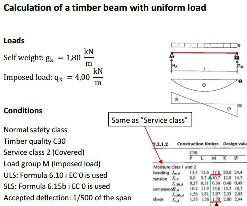
timber beam calculation load uniform deflection span acceptable
Structural Analysis of Reinforced Concrete Beams, Flexural Design of Reinforced Concrete beams, Shear Design of Reinforced Concrete Beams, Check for Cracking in Reinforced Concrete Beams, Design Example of a Reinforced Concrete Beam, minimum areas of steel required in reinforced concrete beams, Design of Reinforced Concrete (R.C) Columns, Construction and Cost Comparison of Rectangular and Trapezoidal Drains, Voided Slab Bridge Decks: Design and Construction, Analysis of Partition Loads on Slabs | Wall Load on Slabs, Cost Comparison of Solid and Ribbed Slabs, Fatigue Verification in RC Bridges (Eurocode 2), See how this Cantilever Design Problem was Solved, Number and Depth of Borings for Soil Investigation, Evaluation of Pykrete in the Design of a Lattice Tower, Structural Analysis and Design of Residential Buildings Using Staad.Pro, Orion, and Manual Calculations. ACI code requirements for placing stirrups: When fvc< vufvc, max s = d/224 in.
T- beams are usually internal beams, while external beams (perimeter beams) are usually L beams.
Strain distribute linearly across the section.
The resultant of compressive stress, C is located at a distance, a/2, from the top surface. Concrete is assumed to resist compression only, tension shall be resisted by reinforcements.
As said earlier, the size is generally chosen from experience. Members not supporting or attached to partitions or other construction likely to be damaged by large deflections, Notes:
Where;CRd,c = 0.18/ck = 1 + (200/d) < 0.02 (d in mm);1 = As1/bd < 0.02 (In which As1 is the area of tensile reinforcement which extends (lbd + d) beyond the section considered)Vmin = 0.035k(3/2)fck0.5K1 = 0.15; cp = NEd/Ac < 0.2fcd(Where NEd is the axial force at the section, Ac = cross sectional area of the concrete), fcd = design compressive strength of the concrete).
Concrete weight = 1.125 x 2400 = 2700 kg.
Shear is at its maximum at the edge of supports.
Effective depth can be computed using beam depth (h).
It is a helping hand to those who are stilling learning the Eurocode and switching from British Standard BS8110. 1 = As/bd = 402/(230 399) = 0.00438 < 0.02; cp = NEd/Ac < 0.2fcd (Where NEd is the axial force at the section, Ac = cross sectional area of the concrete), fcd = design compressive strength of the concrete.) Hi UBANI
Take NEd = 0. There are exceptions in which shear at the face of the support shall be used for shear design. Then, find number of bar by dividing reinforcement area over the area of a single bar. Log in to TheConstructor to ask questions, answer peoples questions, write articles & connect with other people. Table 1: Equivalent UDL load transferred from slab to beam, Where;n = ultimate pressure load on the slab = 1.35gk + 1.5qklx = length of short spanly = length of long spank = ly/lx.
Stirrups (links) are used for resisting any excess shear force and torsion (where applicable). beam chart load w4 flitch calculator
When you join you get additional benefits. For aerated concrete blocks and auto-claved concrete (ACC) blocks, like Aerocon or Siporex, the weight per cubic meter ranges between 550 and 650 kilograms.
Secondly, estimate design concrete shear strength, No shear reinforcement is needed if Vu< 0.5. Lastly, check whether the bar can be placed within selected width of the cross section. For other conditions, the values modified as follows: beam structural calculations relevant send check please Save my name, email, and website in this browser for the next time I comment. Definition: A column is a vertical compression member thats subjected to effective lengths and axial loads of which exceed three times its least lateral dimension. Design of Reinforced Concrete (R.C.) As,min = 0.26 fctm/fyk b d = 0.26 (2.5649/460) 230 399 = 133.04 mm2Check if As,min < 0.0013 b d (119.301 mm2)Since, As,min = 168.587 mm2, the provided reinforcement is adequate.
https://structville.com/2018/02/how-to-calculate-the-effective-flange-of-width-of-beams-according-to-ec2.html, If the continuous beam is L shape does that mean we will design the sagging moments ( Spans ) as L shape ? Concrete Slab weight = 1.125 x 2400 = 2700 kg. Substituting equation (6) into (5) and making As1 the subject of the formula; The lever arm z in EC2 is given from equation (2), z = d 0.4xTherefore, x = 2.5(d z)M = 0.453 fck b 2.5(d z)zLet k = M/(fck bd2)k can be considered as the normalised bending resistanceHence;M/(fck bd2) = 1.1333 [(fck bdz)/(fckbd2) (fck bz2)/(fck bd2)]Therefore;0 = 1.1333[(z/d)2 (z/d)] + k0 = (z/d)2 (z/d) + 0.88235kSolving the quadratic equation;z/d = [1 + (1 3.529k)0.5]/2Rearranging;z = d[0.5 + (0.25 k/1.134)] (8)z = d[0.5 + (0.25 0.882k)]where ;k = MEd/(fckbd2) (9). The magnitude of load transferred depends on if the slab is spanning in one-way or two-way. The value of live load varies according to the type of building for which we have to follow the code IS 875 -1987 part 2. This shift rule may also be used as an alternative for members with shear reinforcement, where: al = z (cot cot)/2 = 0.5z cot for vertical shear linksz = lever arm, = angle of compression strutal = 1.125d when cot = 2.5 and 0.45d when cot = 1. When a reinforced concrete beam fails in yielding of steel, the failure is ductile because the steel can stretch for a long period of time before it actually breaks.
monorail ers ysis flange Beams that are not carrying any slab load are more often rectangular beams. Size of Slab Length 3 m x 2.5 m Thickness 0.150 m, Concrete Volume = 3 x 2.5 x 0.15 = 1.125 m.
Size of columnHeight 2.55 m, Length = 300 mm, Width = 600 mm(2.55m x 300mm x 600mm), Volume of Concrete = 0.30 x 0.60 x 2.55 =0.459 m, Weight of Concrete = 0.459 x 2400 = 1101.60 kg, Weight of Steel (1%) in Concrete=0.459 x 1% x 7850= 36.03 kg, Total Weight of Column = 1101.60 + 36.03 = 1137.63 kg = 11.12 KN. Hello Engineer, please any idea on how we can design a long span beam with columns standing along the span ?
/* Add your own Mailchimp form style overrides in your site stylesheet or in this style block.
Concrete cover = 35mm, fck = 25 MPa, fyk = 460 MPa. Country Types of anchorage are shown in Figure 7 below (Figure 8.1 EC2).
shear calculator mechanicalbase illustrative beam calculator supported simply VRd,c = [0.12 1.708(100 0.00438 25 )1/3] 230 399 = 41767.763 N = 41.767 KN Since VRd,c (41.767) < VEd (65.19 KN), shear reinforcement is required.
The analysis of trapezoidal and triangular loads on beams can be tedious especially for continuous beams with variable loading and unequal spans. Let m = fy/0.85fc, then, a =rdm..The nominal moment strength of the section. Steel Load Calculation. Typically, for a two-way slab, the loads are either triangular (for the beam parallel to the short span direction of the slab) or trapezoidal (for the beam parallel to the long span direction of the slab) as shown in Figure 5. If the headroom of the building is low, you cannot afford very deep sections unless the beams are directly aligned with the partitions. The shear force that is resisted by shear reinforcements is Vs = (Vu -fVc).
At Structville, we stop at nothing in giving you new dimensions to the profession of civil engineering.