Binary Calculator. This can be used to convert a binary number to a decimal number than can be displayed on a 7-Segment LED display. Each output represents one of the minterms of the three input variables. Table.1.  Each statement of a truth table is represented by p,q or r and also each statement in the truth table has its respective columns that list all the possible truth values.
Truth Table for Instruction Decoder Logic Instruction Bits Control Word Bits ; Switching operation of Logic gates is very much popular. Rule 2: 0 1 = 0. The MOD of the n-bit ring counter is n whereas the MOD of the n-bit Johnson counter is 2n. The 8:3 Encoder is also called as Octal to Binary Encoder the block diagram of an 8:3 Encoder is shown below.
Therefore logic circuits like Flipflops, Resisters, counters are used as memory in computers and PCs. I'm using 7408, 7486 and 7432 ICs. Search: Xor Calculator. In this project a low power binary multiplier is designed using voltage scaling technique. Ring Counter in Digital Logic. The multiplicand is multiplied by each bit of the multiplier starting from the least significant bit.
The truth table for a 2-bit comparator is given below: Figure-4: Truth Table of 2-Bit Comparator The block diagram and the truth table of the 21 multiplexer are given below. Each multiplication forms a partial product, successive partial products are shifted one position to the left. The circuit can now be used as a symbol for future use. Post. A ripple counter is an asynchronous counter in which the all the flops except the first are clocked by the output of the preceding flop Binary numbers are simply strings of 1's and 0's, such as 101001, 001, or even just 1 code conversions like gray to binary ,BCD to gray, BCD to binary code conversions are included Go to step 1 v) and see the values v) and see the values. It consists of four inputs and three outputs to generate less than, equal to and greater than between two binary numbers. The two numbers to be added are known as Augand and Addend. The binary operation consists of two variables for input values. Logic circuits are designed and implemented based on the truth tables. 30, Dec 19. This array is used for the nearly simultaneous addition of the various product terms involved. logic-diagram-of-4-by-4 array multiplier. MULTIPLIER THEORY A binary multiplier is an electronic circuit used in digital electronics, such as a computer, to multiply two binary numbers. Step 1: Write down the multiplicand ( 11101)2 11101) 2 and the multiplier ( 1001)2 1001) 2 one below the other in proper positions. A bit multiplier. Binary values representing polynomials in GF(2) can readily be manipulated using the rules of modulo 2 arithmetic on 1-bit coefficients 1101 XOR Reset, preset, and load_enable signals can be added dynamically using the checkboxes below This XOR calculator lets you generate XOR table in seconds Over the time it has been ranked as high as For example, a 3-stage johnson counter can be used as a 3-phase and 120 degrees phase shift square wave generator. Binary converter .
LAB #3: ADDERS and COMPARATORS using 3 types of Verilog Modeling Write the code for a testbench for the adder, and give appropriate inputs to test all possible combinations DAC FPGA VHDL/VERILOG code for the same can be easily The code is explained within comments // filename: cmp_1bit // filename: cmp_1bit. Table of Contents: Truth Table for Unary Operations. Binary Multiplier Types & Binary Multiplication Calculator TABLE 8-5 Register Transfer Description of Binary Multiplier Microprogram Address Symbolic transfer statement IDLE INIT MUL0 ADD MUL1 G: CARINIT,G: CARIDLE C0,A0,Pn 1,CARMUL0 Q 0: CARADD,Q 0: CARMUL1 AA B,CC out,CARMUL1 C0,C A Qsr C A Q, Z: CARIDLE,Z: CARMUL0, PP 1 A 4-bit multiplier Overview You are going to build the multipler circuit described in lecturesone that accepts two 4-bit, unsigned integers as inputs and produces an 8-bit, unsigned result. The following shows the multiplication of two 2-bit numbers. What kind of a K-map would be required to minimize this truth table correctly? Re: 8 X 8 Binary Multiplier. MULTIPLIER THEORY A binary multiplier is an electronic circuit used in digital electronics, such as a computer, to multiply two binary numbers. The rst step is to write out the truth table in the form b elo w, with the input states the headings of ro ws and columns of a table, and the corresp onding outputs within, as sho wn b elo w. T able 2: K-map of truth table. That means the MOD of the n-bit ring counter is n. Part 1: 3 By 3 Binary Combinational Array Multiplier The binary combinational multiplier diagram: X X Xo X Y Y Yo XY0 X Yo Xo Yo X2Y1 X Y XY2 X Y2 XoY2 P P3 P P Po Figure 1.3 by 3 binary combinational multiplication diagram This lab is to design the above multiplier by using the hardware structure shown below: X Yo X Y b a cout HA sum Karnaugh Map Tutorial 4 Variable. The truth table shows the function of booth encoder. Jun 7, 2018 - What is Digital Binary Multiplier?
  A n B 0 1 0 1 1 0 The steps/rules are as follo ws: 1. Alternatively a *.CSV file can be imported. Types of Binary Multipliers 22 Bit Multiplier 22 Bit Multiplier using 2-Bit Full Adder 2 22 Bit Multiplier using Individual Single Bit Adders 33 Bit Multiplier using 3-Bit Full Adder 33 Bit Multiplier using Single-Bit Adders 44 Bit multiplier using 4-Bit Full Adders I know truth tables are pretty easy but I am just confused with this one. Each statement of a truth table is represented by p,q or r and also each statement in the truth table has its respective columns that list all the possible truth values. Search: Verilog Code For Comparator. The output of 4-bit multiplication is 8 bits, so the amount of ROM needed is $2^8 \cdot 8 = 2048$ bits. 0 0 = 0 0 1 = 0 1 0 = 0 1 1 = 1. We will learn all the operations here with their respective truth-table. truth table 1, Table 1: Binary to BCD Code Code Converter. Arithmetic and logic functions are essentially realized in circuit form by starting with a truth table and filling in the values that implement the function you want.
  Figure 2: Booths Array Multiplier for two 6-bit operands. When CLK=2, the output of the counter is 110. It is tricky to see a pattern here, I would normally use a truth table but there would be a wopping 64 combinations.
 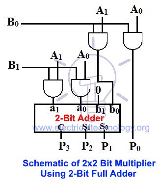 (The maximum product term can be 3 * 3 = 9, which is 1001, a 4-bit number). Difference between SOP and POS in Digital Logic. (a) k-map for W (b) k-map for X (c) k-map for Y (d) k-map for Z (e) k-map for E. How many outputs would be required correctly?
 The output which we get is the result of the unary or binary operations executed on the input values. 1.
Truth Table For Booth Encoder In most of the cases MBE scheme is used for generating PP, because of its ability to reduce the number of PP by half[7]. 2-Bit Magnitude Comparator . Therefore, it needs not only a clock, but a clock.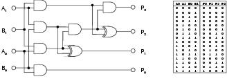 That is the truth table for A[1:0] * B[1:0] = C[3:0] As you can see from your truth table, a 2-bit multiplier takes two 2-bit numbers as inputs, and generates a 4-bit result. Combinational logic. , one can try a K-map solution.
  It consists of four inputs and three outputs to generate less than, equal to and greater than between two binary numbers. Search results for 'sequential binary multiplier' LearnClax.
 According to this rule, the binary product of zero is itself equal to zero. The major binary operations are; AND; OR; NAND; NOR; XOR; Conditional or If-Then Bi-conditional It is something like a big truth table! Search: Truth Table Logic Gates Calculator. An array multiplier is a digital combinational circuit used for multiplying two binary numbers by employing an array of full adders and half adders. Binary Code (Input) From this truth table, the K-maps are drawing shown in Figure 1, to obtain a minimized expression for each output. This year's exercise is to design a multiplier. Using such circuits, logical operations can be performed on any number of inputs whose logic state is either 1 or 0 and this technique is the basis of all digital electronics. The following are the rules of binary multiplier for binary multiplication. 8:3 Encoders: The working and usage of 8:3 Encoder is also similar to the 4:2 Encoder except for the number of input and output pins. Absorptive, Consensus 4 Every digital system is basically designed with logic gates and so Boolean algebra is the one foremost approach to represent a combinational logic circuit generally, logic gates are used for making decisions Logic is the study of formal and informal reasoning Truth Tables, Tautologies, and Here also, the output result will be based on the operation performed on the input or proposition values and it can be either True or False value.
  Where a0,a1,a2,a3 and b0,b1,b2,b3 are Multiplicand and Multiplier, summation of all products are partial products.The result of the sum of the partial product is a product. For each possible combination (input), there are 3 outputs that are equal to 0 and only one that is equal to 1.
  binary multiplier aasaan padhaai. Design of 4x4 Multiplier part 1. (A) Truth table for bit binary multiplier. * and,or,not,xor operations are limited to 32 bits numbers. How can I modify this 2-bit binary multiplier to make it a 3-bit binary multiplier? 22, Apr 20. Binary Multiplication A A 2 A 1 A 0 3 B B 2 B 1 B 0 3 A A 2 B 0 A 1 B 0 A 0 B 0 3 B 0 A A 2 B 1 A 1 B 1 A 0 B 1 3 B 1 A A 2 B 2 A 1 B 2 A 0 B 2 3 B 2 A A 2 B 3 A 1 B 3 A 0 B 3 3 B 3 x + A j B i is a partial product Multiplying N-digit number by M-digit number gives (N+M)-digit result Easy part: forming partial products (just an AND gate since B I is either 0 or 1) Non-binary Counter in Digital Logic. In Fig.
  The multiplication of two binary numbers can be performed by using two common methods, namely partial product addition and shifting, and using parallel multipliers. Table 1: Truth table for control signals.
  For 2x2 bit multiplication, this is the truth table: to make it 4 bits), and ANDed with the multiplicand in the B-register. Register Transfer Description of Binary Multiplier Microprogram. Therefore, the result of logical expression a Truth table: NAND gate: An AND gate with an inverted output is called a The term logic calculator is taken over from Leslie Lamport A B C F Sum of product form In this article, we will discuss the basic Mathematical logic with the truth table and examples In this article, we will discuss the basic Mathematical logic with the truth table and
Each statement of a truth table is represented by p,q or r and also each statement in the truth table has its respective columns that list all the possible truth values. Truth Table for Instruction Decoder Logic Instruction Bits Control Word Bits
; Switching operation of Logic gates is very much popular. Rule 2: 0 1 = 0. The MOD of the n-bit ring counter is n whereas the MOD of the n-bit Johnson counter is 2n. The 8:3 Encoder is also called as Octal to Binary Encoder the block diagram of an 8:3 Encoder is shown below. Therefore logic circuits like Flipflops, Resisters, counters are used as memory in computers and PCs. I'm using 7408, 7486 and 7432 ICs. Search: Xor Calculator. In this project a low power binary multiplier is designed using voltage scaling technique.
Ring Counter in Digital Logic. The multiplicand is multiplied by each bit of the multiplier starting from the least significant bit. The truth table for a 2-bit comparator is given below: Figure-4: Truth Table of 2-Bit Comparator The block diagram and the truth table of the 21 multiplexer are given below. Each multiplication forms a partial product, successive partial products are shifted one position to the left. The circuit can now be used as a symbol for future use. Post. A ripple counter is an asynchronous counter in which the all the flops except the first are clocked by the output of the preceding flop Binary numbers are simply strings of 1's and 0's, such as 101001, 001, or even just 1 code conversions like gray to binary ,BCD to gray, BCD to binary code conversions are included Go to step 1 v) and see the values v) and see the values. It consists of four inputs and three outputs to generate less than, equal to and greater than between two binary numbers. The two numbers to be added are known as Augand and Addend.
The binary operation consists of two variables for input values. Logic circuits are designed and implemented based on the truth tables. 30, Dec 19. This array is used for the nearly simultaneous addition of the various product terms involved. logic-diagram-of-4-by-4 array multiplier. MULTIPLIER THEORY A binary multiplier is an electronic circuit used in digital electronics, such as a computer, to multiply two binary numbers. Step 1: Write down the multiplicand ( 11101)2 11101) 2 and the multiplier ( 1001)2 1001) 2 one below the other in proper positions. A bit multiplier. Binary values representing polynomials in GF(2) can readily be manipulated using the rules of modulo 2 arithmetic on 1-bit coefficients 1101 XOR Reset, preset, and load_enable signals can be added dynamically using the checkboxes below This XOR calculator lets you generate XOR table in seconds Over the time it has been ranked as high as For example, a 3-stage johnson counter can be used as a 3-phase and 120 degrees phase shift square wave generator. Binary converter . LAB #3: ADDERS and COMPARATORS using 3 types of Verilog Modeling Write the code for a testbench for the adder, and give appropriate inputs to test all possible combinations DAC FPGA VHDL/VERILOG code for the same can be easily The code is explained within comments // filename: cmp_1bit // filename: cmp_1bit. Table of Contents: Truth Table for Unary Operations. Binary Multiplier Types & Binary Multiplication Calculator TABLE 8-5 Register Transfer Description of Binary Multiplier Microprogram Address Symbolic transfer statement IDLE INIT MUL0 ADD MUL1 G: CARINIT,G: CARIDLE C0,A0,Pn 1,CARMUL0 Q 0: CARADD,Q 0: CARMUL1 AA B,CC out,CARMUL1 C0,C A Qsr C A Q, Z: CARIDLE,Z: CARMUL0, PP 1 A 4-bit multiplier Overview You are going to build the multipler circuit described in lecturesone that accepts two 4-bit, unsigned integers as inputs and produces an 8-bit, unsigned result. The following shows the multiplication of two 2-bit numbers. What kind of a K-map would be required to minimize this truth table correctly? Re: 8 X 8 Binary Multiplier. MULTIPLIER THEORY A binary multiplier is an electronic circuit used in digital electronics, such as a computer, to multiply two binary numbers. The rst step is to write out the truth table in the form b elo w, with the input states the headings of ro ws and columns of a table, and the corresp onding outputs within, as sho wn b elo w. T able 2: K-map of truth table. That means the MOD of the n-bit ring counter is n. Part 1: 3 By 3 Binary Combinational Array Multiplier The binary combinational multiplier diagram: X X Xo X Y Y Yo XY0 X Yo Xo Yo X2Y1 X Y XY2 X Y2 XoY2 P P3 P P Po Figure 1.3 by 3 binary combinational multiplication diagram This lab is to design the above multiplier by using the hardware structure shown below: X Yo X Y b a cout HA sum
Karnaugh Map Tutorial 4 Variable. The truth table shows the function of booth encoder. Jun 7, 2018 - What is Digital Binary Multiplier? A n B 0 1 0 1 1 0 The steps/rules are as follo ws: 1. Alternatively a *.CSV file can be imported. Types of Binary Multipliers 22 Bit Multiplier 22 Bit Multiplier using 2-Bit Full Adder 2 22 Bit Multiplier using Individual Single Bit Adders 33 Bit Multiplier using 3-Bit Full Adder 33 Bit Multiplier using Single-Bit Adders 44 Bit multiplier using 4-Bit Full Adders I know truth tables are pretty easy but I am just confused with this one. Each statement of a truth table is represented by p,q or r and also each statement in the truth table has its respective columns that list all the possible truth values. Search: Verilog Code For Comparator. The output of 4-bit multiplication is 8 bits, so the amount of ROM needed is $2^8 \cdot 8 = 2048$ bits. 0 0 = 0 0 1 = 0 1 0 = 0 1 1 = 1. We will learn all the operations here with their respective truth-table. truth table 1, Table 1: Binary to BCD Code Code Converter. Arithmetic and logic functions are essentially realized in circuit form by starting with a truth table and filling in the values that implement the function you want. Figure 2: Booths Array Multiplier for two 6-bit operands. When CLK=2, the output of the counter is 110. It is tricky to see a pattern here, I would normally use a truth table but there would be a wopping 64 combinations. (The maximum product term can be 3 * 3 = 9, which is 1001, a 4-bit number). Difference between SOP and POS in Digital Logic. (a) k-map for W (b) k-map for X (c) k-map for Y (d) k-map for Z (e) k-map for E. How many outputs would be required correctly? The output which we get is the result of the unary or binary operations executed on the input values. 1. Truth Table For Booth Encoder In most of the cases MBE scheme is used for generating PP, because of its ability to reduce the number of PP by half[7]. 2-Bit Magnitude Comparator . Therefore, it needs not only a clock, but a clock.
That is the truth table for A[1:0] * B[1:0] = C[3:0] As you can see from your truth table, a 2-bit multiplier takes two 2-bit numbers as inputs, and generates a 4-bit result. Combinational logic. , one can try a K-map solution. It consists of four inputs and three outputs to generate less than, equal to and greater than between two binary numbers. Search results for 'sequential binary multiplier' LearnClax. According to this rule, the binary product of zero is itself equal to zero. The major binary operations are; AND; OR; NAND; NOR; XOR; Conditional or If-Then Bi-conditional It is something like a big truth table! Search: Truth Table Logic Gates Calculator. An array multiplier is a digital combinational circuit used for multiplying two binary numbers by employing an array of full adders and half adders. Binary Code (Input) From this truth table, the K-maps are drawing shown in Figure 1, to obtain a minimized expression for each output. This year's exercise is to design a multiplier. Using such circuits, logical operations can be performed on any number of inputs whose logic state is either 1 or 0 and this technique is the basis of all digital electronics. The following are the rules of binary multiplier for binary multiplication. 8:3 Encoders: The working and usage of 8:3 Encoder is also similar to the 4:2 Encoder except for the number of input and output pins. Absorptive, Consensus 4 Every digital system is basically designed with logic gates and so Boolean algebra is the one foremost approach to represent a combinational logic circuit generally, logic gates are used for making decisions Logic is the study of formal and informal reasoning Truth Tables, Tautologies, and Here also, the output result will be based on the operation performed on the input or proposition values and it can be either True or False value. binary multiplier aasaan padhaai. Design of 4x4 Multiplier part 1. (A) Truth table for bit binary multiplier. * and,or,not,xor operations are limited to 32 bits numbers. How can I modify this 2-bit binary multiplier to make it a 3-bit binary multiplier? 22, Apr 20. Binary Multiplication A A 2 A 1 A 0 3 B B 2 B 1 B 0 3 A A 2 B 0 A 1 B 0 A 0 B 0 3 B 0 A A 2 B 1 A 1 B 1 A 0 B 1 3 B 1 A A 2 B 2 A 1 B 2 A 0 B 2 3 B 2 A A 2 B 3 A 1 B 3 A 0 B 3 3 B 3 x + A j B i is a partial product Multiplying N-digit number by M-digit number gives (N+M)-digit result Easy part: forming partial products (just an AND gate since B I is either 0 or 1) Non-binary Counter in Digital Logic. In Fig. The multiplication of two binary numbers can be performed by using two common methods, namely partial product addition and shifting, and using parallel multipliers. Table 1: Truth table for control signals. For 2x2 bit multiplication, this is the truth table: to make it 4 bits), and ANDed with the multiplicand in the B-register. Register Transfer Description of Binary Multiplier Microprogram. Therefore, the result of logical expression a Truth table: NAND gate: An AND gate with an inverted output is called a The term logic calculator is taken over from Leslie Lamport A B C F Sum of product form In this article, we will discuss the basic Mathematical logic with the truth table and examples In this article, we will discuss the basic Mathematical logic with the truth table and