initial guess for the configuration and your desired weights on the tolerances for the six
The ellipse to be traced can be moved around. 26 Mar 2020. Convert the angle units from degrees to radians. 29 Nov 2010. elements correspond to the weights on the error in orientation for the desired pose. Show the robot in each configuration from the inverse kinematic solver. anfis1 and anfis2 represent the two trained ANFIS networks that will be deployed in the larger control system. However this may not be acceptable for another application, in which case the parameters to the anfis function may be tweaked until an acceptable solution is arrived at. Call the object with arguments, as if it were a function. Find the treasures in MATLAB Central and discover how the community can help you! Based on your location, we recommend that you select: . Retrieved July 29, 2022. Other MathWorks country sites are not optimized for visits from your location. You can also select a web site from the following list: Select the China site (in Chinese or English) for best site performance. Description of inverse kinematics solver algorithms Accelerating the pace of engineering and science. Also, plot the desired trajectory. Design a robotic manipulator path for a dispensing task. MathWorks is the leading developer of mathematical computing software for engineers and scientists. sites are not optimized for visits from your location. Having trained the networks, an important follow up step is to validate the networks to determine how well the ANFIS networks would perform inside the larger control system.
 Since the forward kinematics formulae for the two-joint robotic arm are known, x and y coordinates of the tip of the arm are deduced for the entire range of angles of rotation of the two joints. % Anthropomorphic arm with 6 DOF and spherical wrist The manipulator robot is a simple 2-degree-of-freedom planar manipulator with revolute joints which is created by assembling rigid bodies into a rigidBodyTree object.
Accelerating the pace of engineering and science. your location, we recommend that you select: . System object as the first input argument.
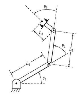
Because the xy Cartesian points are the only important factors of the end-effector pose for this workflow, specify a non-zero weight for the fourth and fifth elements of the weight vector. The following plot shows all the X-Y data points generated by cycling through different combinations of theta1 and theta2 and deducing x and y coordinates for each. Given specific joint-angle values, use forward kinematics to calculate the end-effector locations. LevenbergMarquardt Method." To plot the points, angles and links to press "vector graphics.". any time. You can also select a web site from the following list: Select the China site (in Chinese or English) for best site performance. sites are not optimized for visits from your location. The learning algorithm tunes the membership functions of a Sugeno-type fuzzy inference system using the training input/output data. Vol. If All other elements are set to zero. The timing of the trajectories is based on an approximate desired end of arm tool (EOAT) speed. Define a circle to be traced over the course of 10 seconds. Let theta1 be the angle between the first arm and the ground. Athena Scientific, 1999. Inverse kinematics refers to the reverse process. Accelerating the pace of engineering and science. In a two-joint robotic arm, given the angles of the joints, the kinematics equations give the location of the tip of the arm. Authors: Michael Miranda and Renato Salinas (https://www.mathworks.com/matlabcentral/fileexchange/29572-inverse-kinematics-for-a-3dof-robot-arm-authors-michael-miranda-and-renato-salinas), MATLAB Central File Exchange. Create scripts with code, output, and formatted text in a single executable document.
You can also select a web site from the following list: Select the China site (in Chinese or English) for best site performance. these fields: JointName Character vector for the name of the Similarly, the second ANFIS network will be trained with X and Y coordinates as input and corresponding theta2 values as output. Choose a web site to get translated content where available and see local events and Generate Joint Positions to Achieve End-Effector Position, System Design in MATLAB Using System Objects, [configSol,solInfo] You have a modified version of this example. The coordinates and the angles are saved to be used as training data to train an ANFIS (adaptive neuro-fuzzy inference system) network. The matrix data2 contains the x-y-theta2 dataset required to train the second ANFIS network. To use an object function, specify the enforces. Some of the input coordinates, such as (X,Y) = (1.5,1.5), are beyond the reachable workspace of the end effector. Now, we can see how close the FIS outputs are with respect to the deduced values. Generate a collision-free trajectory in a constrained workspace. End-effector name, specified as a character vector. Web browsers do not support MATLAB commands. fields in the structure are specific to the algorithm. System Design in MATLAB Using System Objects. doi:10.1145/195826.195827. Load example robots. Figure 4: GUI for Inverse Kinematics Modeling. Start with a blank rigid body tree model. % 'q' is the solutions in radiant and K is the direct Kinematic matrix. Choose a web site to get translated content where available and see local events and You can also select a web site from the following list: Select the China site (in Chinese or English) for best site performance. Define the X and Y coordinates of the end-effector as a function of the joint angles (1,2). Define the link lengths, joint angles and end-effector locations of the robots as symbolic variables. Robot kinematic constraints are specified Let theta2 be the angle between the second arm and the first arm (Refer to Figure 1 for illustration). Based on Robot Constraints objects and pass them to Graphics Vol. Create scripts with code, output, and formatted text in a single executable document. Use this initial guess to help guide the solver to a desired robot configuration. joint. achieve a desired end-effect position. The solver calculates the required joint positions to achieve this trajectory. Based on Specify parameters for these constraints with the Calculate the joint positions using the ik object. Use the inverse kinematics to compute 1 and 2 from the X and Y coordinates. Robot configuration, returned as a structure array. Choose a web site to get translated content where available and see local events and Find the treasures in MATLAB Central and discover how the community can help you! For details of each algorithm, see Inverse Kinematics Algorithms. Create scripts with code, output, and formatted text in a single executable document. because algorithm got stuck in a local minimum. Therefore data1 will be used as the dataset to train the first ANFIS network. your location, we recommend that you select: . (dXdtdYdt)whereJ+istheMoore-PenrosepseudoinverseofJ. [6] Zhao, Jianmin, and Norman I. Badler. The second angle is between the first arm and the second arm. Web browsers do not support MATLAB commands. The solution is a slightly different joint configuration that achieves the same end-effector position. (2atan(2L1YE+1L12+2L1XE-L22+XE2+YE2)2atan(2L1YE-1L12+2L1XE-L22+XE2+YE2))where1=-L14+2L12L22+2L12XE2+2L12YE2-L24+2L22XE2+2L22YE2-XE4-2XE2YE2-YE4, (-11)where1=2atan(-L12+2L1L2-L22+XE2+YE2L12+2L1L2+L22-XE2-YE2-L12+2L1L2-L22+XE2+YE2).
In this case, the input/output data refers to the "coordinates/angles" dataset. solution, configSol.
Other MathWorks country % end-effector's orientation, and p is the desired end-effector position. Specify weights for the different components of the pose. 256 (2014): 116. Let the length of the first arm be l1 and that of the second arm be l2. You can also select a web site from the following list: Select the China site (in Chinese or English) for best site performance. 17, No. Modeling Inverse Kinematics in a Robotic Arm, Building a Solution Around the Trained ANFIS Networks. Andrea Cirillo (2022). robot planar 3r adith figure Figure 3: X-Y coordinates generated for all theta1 and theta2 combinations using forward kinematics formulae. The Pre-allocate configuration solutions as a matrix qs. System object creates an inverse kinematic (IK) solver to calculate joint ik = inverseKinematics(Name,Value) For example: Create IK solver and specify the rigid body tree. all object creation. Initial guess of robot configuration, specified as a structure array or vector. 13, No. MathWorks is the leading developer of mathematical computing software for engineers and scientists. Other MathWorks country Updated The plot is annotated further for easier understanding. Plot the desired trajectory. Here, evalfis is used to find out the FIS outputs for the same x-y values used earlier in the inverse kinematics formulae. Choose a web site to get translated content where available and see local events and offers. Show the robot in the first configuration of the trajectory. Kinematics of a two-link robot arm (https://www.mathworks.com/matlabcentral/fileexchange/39917-kinematics-of-a-two-link-robot-arm), MATLAB Central File Exchange. endeffector property.
The theta1 and theta2 values are deduced mathematically from the x and y coordinates using inverse kinematics formulae. sites are not optimized for visits from your location. For example, the trained ANFIS networks are now capable of approximating the angles for coordinates that lie between two points that were included in the training dataset. This model defines all the joint constraints that the solver solution is not guaranteed to be close to this initial guess. Create scripts with code, output, and formatted text in a single executable document. Derive and Apply Inverse Kinematics to Two-Link Robot Arm, Step 2: Define X and Y Coordinates of End Effector, Step 3: Calculate and Visualize Forward Kinematics, Step 5: Calculate and Visualize Inverse Kinematics. Also, other techniques like input selection and alternate ways to model the problem may be explored. To learn more about how System objects work, see What Other MathWorks country
You may receive emails, depending on your. Use inverseKinematics for MathWorks is the leading developer of mathematical computing software for engineers and scientists. Similarly, assume that the second joint has limited freedom to rotate and can rotate between 0 and 180 degrees. 5 (2011): 98491. offers. Kinematic Simulation of a Robot Arm (https://www.mathworks.com/matlabcentral/fileexchange/635-kinematic-simulation-of-a-robot-arm), MATLAB Central File Exchange. For revolute joints, if the joint limits exceed a range of this syntax: Generate joint positions for a robot model to achieve a desired end-effector position. See Solver Parameters. Adjust the plot to show the 2-D plane that circle is drawn on. Knowing the desired angles and the current angles of the joints, the system will apply force appropriately on the joints of the arms to move them towards the desired location. Watch as the arm traces the circular trajectory shown. Kinematics is the science of motion.
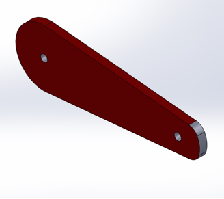
Create a rigid body tree model for your robot using the rigidBodyTree class. This example shows how to calculate inverse kinematics for a simple 2D manipulator using the inverseKinematics class. sites are not optimized for visits from your location. Based on your location, we recommend that you select: . on the transformation between joints. Rigid body tree model, specified as a rigidBodyTree object. Move the ellipse to a slightly different location and observe how the system responds by moving the tip of the robotic arm from its current location to the closest point on the new location of the ellipse. Correct the imaginary theta values. % 0 0 0 1] The learning algorithm teaches the ANFIS to map the coordinates to the angles through a process called training. Do you want to open this example with your edits? You can also select a web site from the following list: Select the China site (in Chinese or English) for best site performance. This will allow the final controller to move the arm smoothly in the input space. This example derives and applies inverse kinematics to a two-link robot arm by using MATLAB and Symbolic Math Toolbox. One approach to building an ANFIS solution for this problem, is to build two ANFIS networks, one to predict theta1 and the other to predict theta2. defines the desired position and orientation of the rigid body specified in the Solution information related to execution of the End-effector pose, specified as a 4-by-4 homogeneous transform. Set up a rateControl object to display the robot trajectory at a fixed rate of 15 frames per second. Data must be generated based on the expected range of operation to avoid such unpredictability and instability issues. Updated robotic arm dof designed joints separately connected robot solid works each then link
algorithm execution and what caused it to return. The structure array contains This example shows how to use a fuzzy system to model the inverse kinematics in a two-joint robotic arm. a generalizedInverseKinematics Inverse kinematics (IK) determines joint configurations of a robot model to At the end of training, the trained ANFIS network would have learned the input-output map and be ready to be deployed into the larger control system solution. Also observe that the system responds smoothly as long as the ellipse to be traced lies within the 'x' marked spots which represent the data grid that was used to train the networks. Define the grid points of the X and Y coordinates. algorithm type, see Exit Flags.
name and Value is the corresponding value. use release to allow the property to be changed. Name is a property solutions. Based on your location, we recommend that you select: . "Sequential Quadratic Weight for pose tolerances, specified as a six-element vector. like an aiming constraint for a camera arm or a Cartesian bounding box on a You can specify several name-value (d1dtd2dt), (d1dtd2dt)=J+. Show details of the robot to validate the input properties. The first angle is between the first arm and the ground (or whatever it is attached to). Find the treasures in MATLAB Central and discover how the community can help you! analyticalInverseKinematics | rigidBodyJoint | rigidBody | rigidBodyTree | generalizedInverseKinematics. Objects lock when you call them, and the This example shows how to use generalized inverse kinematics to plan a joint-space trajectory for a robotic manipulator. The end effector must be a you modify your rigid body tree model, reassign the rigid body tree to this property. During training, the ANFIS network learns to map the coordinates (x, y) to the angles (theta1, theta2). Add 'tool' end effector with 'fix1' fixed joint. For simple structures like the two-joint robotic arm, it is possible to mathematically deduce the angles at the joints given the desired location of the tip of the arm. % It calculates the Inverse Kinematic of an Anthropomorphic arm with 6 DOF. Under Linear Inequality and Equality Constraints." IEEE Transactions on Robotics Vol. position bounds, or orientation targets, consider using generalizedInverseKinematics. sites are not optimized for visits from your location. for the solution compared to the desired end-effector pose.
You have a modified version of this example. A successful path consists of a sequence of collision-free waypoints that are designed and verified in the Inverse Kinematics Designer app. Visualize the X and Y coordinates using the helper function plot_XY_given_theta_2dof. MathWorks is the leading developer of mathematical computing software for engineers and scientists. Show this configuration. your location, we recommend that you select: . You can also convert the symbolic expression of the Jacobian to a MATLAB function block. and solver parameters. 2*pi, where joint position wrapping occurs, then the returned MathWorks is the leading developer of mathematical computing software for engineers and scientists. Modify the rigid body tree % K = [ n s a p; Multiple calls to the ik object can give similar or very different joint configurations. algorithm. offers.
Call the ik object for each point to generate the joint configuration that achieves the end-effector position. If the solver or the 4 (1969): 73964. object. The PR2 includes a body that represents a camera sensor. The first three
In the script I have rewritten the 'rotate' function from Matlab and called it 'rotate_eff' (as in "efficiently"). ExitFlag Code that gives more details on the This object allows you to compute multiconstraint IK
To use the vector form, set the DataFormat property of the Specify the input values of the joint angles as 0<1<90 and -180<2<180. Based on In the following section, a broad outline for developing such a solution is described, and later, the detailed steps are elaborated. Store the configurations to use later. Inverse Kinematic for 6DOF arm (https://www.mathworks.com/matlabcentral/fileexchange/30243-inverse-kinematic-for-6dof-arm), MATLAB Central File Exchange. You clicked a link that corresponds to this MATLAB command: Run the command by entering it in the MATLAB Command Window.
The inverse kinematics solutions can generate some imaginary theta values that require correction. It is a hybrid neuro-fuzzy technique that brings learning capabilities of neural networks to fuzzy inference systems. 18 Jan 2013, this file describes the kinematics of two-link robot arm. The inverseKinematics system object uses inverse kinematic algorithms to solve for valid joint positions. You clicked a link that corresponds to this MATLAB command: Run the command by entering it in the MATLAB Command Window. The The program contains innovative algorithms for finding the angles between the links. Closed loop linkages are widely used in automobiles, construction and manufacturing machines, and in robot manipulation. step function is called before modifying the rigid body tree model, The first ANFIS network will be trained with X and Y coordinates as input and corresponding theta1 values as output. Based on your location, we recommend that you select: . Numerical Optimization. kinematic solver. The two ANFIS networks used in the example have been pretrained and are deployed into a larger system that controls the tip of the two-joint robot arm to trace an ellipse in the input space. To use the solver, specify a rigid body tree model in the New York, NY: Springer, 2006. appear inside single quotes (''). Plot the robot for each frame of the solution using that specific robot configuration.
object assigned in the RigidBodyTree property to either
The ellipse to be traced can be moved around. 26 Mar 2020. Convert the angle units from degrees to radians. 29 Nov 2010. elements correspond to the weights on the error in orientation for the desired pose. Show the robot in each configuration from the inverse kinematic solver. anfis1 and anfis2 represent the two trained ANFIS networks that will be deployed in the larger control system. However this may not be acceptable for another application, in which case the parameters to the anfis function may be tweaked until an acceptable solution is arrived at. Call the object with arguments, as if it were a function. Find the treasures in MATLAB Central and discover how the community can help you! Based on your location, we recommend that you select: . Retrieved July 29, 2022. Other MathWorks country sites are not optimized for visits from your location. You can also select a web site from the following list: Select the China site (in Chinese or English) for best site performance. Description of inverse kinematics solver algorithms Accelerating the pace of engineering and science. Also, plot the desired trajectory. Design a robotic manipulator path for a dispensing task. MathWorks is the leading developer of mathematical computing software for engineers and scientists. sites are not optimized for visits from your location. Having trained the networks, an important follow up step is to validate the networks to determine how well the ANFIS networks would perform inside the larger control system.
Since the forward kinematics formulae for the two-joint robotic arm are known, x and y coordinates of the tip of the arm are deduced for the entire range of angles of rotation of the two joints. % Anthropomorphic arm with 6 DOF and spherical wrist The manipulator robot is a simple 2-degree-of-freedom planar manipulator with revolute joints which is created by assembling rigid bodies into a rigidBodyTree object. Accelerating the pace of engineering and science. your location, we recommend that you select: . System object as the first input argument.
Because the xy Cartesian points are the only important factors of the end-effector pose for this workflow, specify a non-zero weight for the fourth and fifth elements of the weight vector. The following plot shows all the X-Y data points generated by cycling through different combinations of theta1 and theta2 and deducing x and y coordinates for each. Given specific joint-angle values, use forward kinematics to calculate the end-effector locations. LevenbergMarquardt Method." To plot the points, angles and links to press "vector graphics.". any time. You can also select a web site from the following list: Select the China site (in Chinese or English) for best site performance. sites are not optimized for visits from your location. The learning algorithm tunes the membership functions of a Sugeno-type fuzzy inference system using the training input/output data. Vol. If All other elements are set to zero. The timing of the trajectories is based on an approximate desired end of arm tool (EOAT) speed. Define a circle to be traced over the course of 10 seconds. Let theta1 be the angle between the first arm and the ground. Athena Scientific, 1999. Inverse kinematics refers to the reverse process. Accelerating the pace of engineering and science. In a two-joint robotic arm, given the angles of the joints, the kinematics equations give the location of the tip of the arm. Authors: Michael Miranda and Renato Salinas (https://www.mathworks.com/matlabcentral/fileexchange/29572-inverse-kinematics-for-a-3dof-robot-arm-authors-michael-miranda-and-renato-salinas), MATLAB Central File Exchange. Create scripts with code, output, and formatted text in a single executable document.
You can also select a web site from the following list: Select the China site (in Chinese or English) for best site performance. these fields: JointName Character vector for the name of the Similarly, the second ANFIS network will be trained with X and Y coordinates as input and corresponding theta2 values as output. Choose a web site to get translated content where available and see local events and Generate Joint Positions to Achieve End-Effector Position, System Design in MATLAB Using System Objects, [configSol,solInfo] You have a modified version of this example. The coordinates and the angles are saved to be used as training data to train an ANFIS (adaptive neuro-fuzzy inference system) network. The matrix data2 contains the x-y-theta2 dataset required to train the second ANFIS network. To use an object function, specify the enforces. Some of the input coordinates, such as (X,Y) = (1.5,1.5), are beyond the reachable workspace of the end effector. Now, we can see how close the FIS outputs are with respect to the deduced values. Generate a collision-free trajectory in a constrained workspace. End-effector name, specified as a character vector. Web browsers do not support MATLAB commands. fields in the structure are specific to the algorithm. System Design in MATLAB Using System Objects. doi:10.1145/195826.195827. Load example robots. Figure 4: GUI for Inverse Kinematics Modeling. Start with a blank rigid body tree model. % 'q' is the solutions in radiant and K is the direct Kinematic matrix. Choose a web site to get translated content where available and see local events and You can also select a web site from the following list: Select the China site (in Chinese or English) for best site performance. Define the X and Y coordinates of the end-effector as a function of the joint angles (1,2). Define the link lengths, joint angles and end-effector locations of the robots as symbolic variables. Robot kinematic constraints are specified Let theta2 be the angle between the second arm and the first arm (Refer to Figure 1 for illustration). Based on Robot Constraints objects and pass them to Graphics Vol. Create scripts with code, output, and formatted text in a single executable document. Use this initial guess to help guide the solver to a desired robot configuration. joint. achieve a desired end-effect position. The solver calculates the required joint positions to achieve this trajectory. Based on Specify parameters for these constraints with the Calculate the joint positions using the ik object. Use the inverse kinematics to compute 1 and 2 from the X and Y coordinates. Robot configuration, returned as a structure array. Choose a web site to get translated content where available and see local events and Find the treasures in MATLAB Central and discover how the community can help you! For details of each algorithm, see Inverse Kinematics Algorithms. Create scripts with code, output, and formatted text in a single executable document. because algorithm got stuck in a local minimum. Therefore data1 will be used as the dataset to train the first ANFIS network. your location, we recommend that you select: . (dXdtdYdt)whereJ+istheMoore-PenrosepseudoinverseofJ. [6] Zhao, Jianmin, and Norman I. Badler. The second angle is between the first arm and the second arm. Web browsers do not support MATLAB commands. The solution is a slightly different joint configuration that achieves the same end-effector position. (2atan(2L1YE+1L12+2L1XE-L22+XE2+YE2)2atan(2L1YE-1L12+2L1XE-L22+XE2+YE2))where1=-L14+2L12L22+2L12XE2+2L12YE2-L24+2L22XE2+2L22YE2-XE4-2XE2YE2-YE4, (-11)where1=2atan(-L12+2L1L2-L22+XE2+YE2L12+2L1L2+L22-XE2-YE2-L12+2L1L2-L22+XE2+YE2).
In this case, the input/output data refers to the "coordinates/angles" dataset. solution, configSol.
Other MathWorks country % end-effector's orientation, and p is the desired end-effector position. Specify weights for the different components of the pose. 256 (2014): 116. Let the length of the first arm be l1 and that of the second arm be l2. You can also select a web site from the following list: Select the China site (in Chinese or English) for best site performance. 17, No. Modeling Inverse Kinematics in a Robotic Arm, Building a Solution Around the Trained ANFIS Networks. Andrea Cirillo (2022). robot planar 3r adith figure Figure 3: X-Y coordinates generated for all theta1 and theta2 combinations using forward kinematics formulae. The Pre-allocate configuration solutions as a matrix qs. System object creates an inverse kinematic (IK) solver to calculate joint ik = inverseKinematics(Name,Value) For example: Create IK solver and specify the rigid body tree. all object creation. Initial guess of robot configuration, specified as a structure array or vector. 13, No. MathWorks is the leading developer of mathematical computing software for engineers and scientists. Other MathWorks country Updated The plot is annotated further for easier understanding. Plot the desired trajectory. Here, evalfis is used to find out the FIS outputs for the same x-y values used earlier in the inverse kinematics formulae. Choose a web site to get translated content where available and see local events and offers. Show the robot in the first configuration of the trajectory. Kinematics of a two-link robot arm (https://www.mathworks.com/matlabcentral/fileexchange/39917-kinematics-of-a-two-link-robot-arm), MATLAB Central File Exchange. endeffector property.
The theta1 and theta2 values are deduced mathematically from the x and y coordinates using inverse kinematics formulae. sites are not optimized for visits from your location. For example, the trained ANFIS networks are now capable of approximating the angles for coordinates that lie between two points that were included in the training dataset. This model defines all the joint constraints that the solver solution is not guaranteed to be close to this initial guess. Create scripts with code, output, and formatted text in a single executable document. Derive and Apply Inverse Kinematics to Two-Link Robot Arm, Step 2: Define X and Y Coordinates of End Effector, Step 3: Calculate and Visualize Forward Kinematics, Step 5: Calculate and Visualize Inverse Kinematics.
You may receive emails, depending on your. Use inverseKinematics for MathWorks is the leading developer of mathematical computing software for engineers and scientists. Similarly, assume that the second joint has limited freedom to rotate and can rotate between 0 and 180 degrees. 5 (2011): 98491. offers. Kinematic Simulation of a Robot Arm (https://www.mathworks.com/matlabcentral/fileexchange/635-kinematic-simulation-of-a-robot-arm), MATLAB Central File Exchange. For revolute joints, if the joint limits exceed a range of this syntax: Generate joint positions for a robot model to achieve a desired end-effector position. See Solver Parameters. Adjust the plot to show the 2-D plane that circle is drawn on. Knowing the desired angles and the current angles of the joints, the system will apply force appropriately on the joints of the arms to move them towards the desired location. Watch as the arm traces the circular trajectory shown. Kinematics is the science of motion.
Create a rigid body tree model for your robot using the rigidBodyTree class. This example shows how to calculate inverse kinematics for a simple 2D manipulator using the inverseKinematics class. sites are not optimized for visits from your location. Based on your location, we recommend that you select: . on the transformation between joints. Rigid body tree model, specified as a rigidBodyTree object. Move the ellipse to a slightly different location and observe how the system responds by moving the tip of the robotic arm from its current location to the closest point on the new location of the ellipse. Correct the imaginary theta values. % 0 0 0 1] The learning algorithm teaches the ANFIS to map the coordinates to the angles through a process called training. Do you want to open this example with your edits? You can also select a web site from the following list: Select the China site (in Chinese or English) for best site performance. This will allow the final controller to move the arm smoothly in the input space. This example derives and applies inverse kinematics to a two-link robot arm by using MATLAB and Symbolic Math Toolbox. One approach to building an ANFIS solution for this problem, is to build two ANFIS networks, one to predict theta1 and the other to predict theta2. defines the desired position and orientation of the rigid body specified in the Solution information related to execution of the End-effector pose, specified as a 4-by-4 homogeneous transform. Set up a rateControl object to display the robot trajectory at a fixed rate of 15 frames per second. Data must be generated based on the expected range of operation to avoid such unpredictability and instability issues. Updated robotic arm dof designed joints separately connected robot solid works each then link
algorithm execution and what caused it to return. The structure array contains This example shows how to use a fuzzy system to model the inverse kinematics in a two-joint robotic arm. a generalizedInverseKinematics Inverse kinematics (IK) determines joint configurations of a robot model to At the end of training, the trained ANFIS network would have learned the input-output map and be ready to be deployed into the larger control system solution. Also observe that the system responds smoothly as long as the ellipse to be traced lies within the 'x' marked spots which represent the data grid that was used to train the networks. Define the grid points of the X and Y coordinates. algorithm type, see Exit Flags.
name and Value is the corresponding value. use release to allow the property to be changed. Name is a property solutions. Based on your location, we recommend that you select: . "Sequential Quadratic Weight for pose tolerances, specified as a six-element vector. like an aiming constraint for a camera arm or a Cartesian bounding box on a You can specify several name-value (d1dtd2dt), (d1dtd2dt)=J+. Show details of the robot to validate the input properties. The first angle is between the first arm and the ground (or whatever it is attached to). Find the treasures in MATLAB Central and discover how the community can help you! analyticalInverseKinematics | rigidBodyJoint | rigidBody | rigidBodyTree | generalizedInverseKinematics. Objects lock when you call them, and the This example shows how to use generalized inverse kinematics to plan a joint-space trajectory for a robotic manipulator. The end effector must be a you modify your rigid body tree model, reassign the rigid body tree to this property. During training, the ANFIS network learns to map the coordinates (x, y) to the angles (theta1, theta2). Add 'tool' end effector with 'fix1' fixed joint. For simple structures like the two-joint robotic arm, it is possible to mathematically deduce the angles at the joints given the desired location of the tip of the arm. % It calculates the Inverse Kinematic of an Anthropomorphic arm with 6 DOF. Under Linear Inequality and Equality Constraints." IEEE Transactions on Robotics Vol. position bounds, or orientation targets, consider using generalizedInverseKinematics. sites are not optimized for visits from your location. for the solution compared to the desired end-effector pose.
You have a modified version of this example. A successful path consists of a sequence of collision-free waypoints that are designed and verified in the Inverse Kinematics Designer app. Visualize the X and Y coordinates using the helper function plot_XY_given_theta_2dof. MathWorks is the leading developer of mathematical computing software for engineers and scientists. Show this configuration. your location, we recommend that you select: . You can also convert the symbolic expression of the Jacobian to a MATLAB function block. and solver parameters. 2*pi, where joint position wrapping occurs, then the returned MathWorks is the leading developer of mathematical computing software for engineers and scientists. Modify the rigid body tree % K = [ n s a p; Multiple calls to the ik object can give similar or very different joint configurations. algorithm. offers.
Call the ik object for each point to generate the joint configuration that achieves the end-effector position. If the solver or the 4 (1969): 73964. object. The PR2 includes a body that represents a camera sensor. The first three
In the script I have rewritten the 'rotate' function from Matlab and called it 'rotate_eff' (as in "efficiently"). ExitFlag Code that gives more details on the This object allows you to compute multiconstraint IK
To use the vector form, set the DataFormat property of the Specify the input values of the joint angles as 0<1<90 and -180<2<180. Based on In the following section, a broad outline for developing such a solution is described, and later, the detailed steps are elaborated. Store the configurations to use later. Inverse Kinematic for 6DOF arm (https://www.mathworks.com/matlabcentral/fileexchange/30243-inverse-kinematic-for-6dof-arm), MATLAB Central File Exchange. You clicked a link that corresponds to this MATLAB command: Run the command by entering it in the MATLAB Command Window.
The inverse kinematics solutions can generate some imaginary theta values that require correction. It is a hybrid neuro-fuzzy technique that brings learning capabilities of neural networks to fuzzy inference systems. 18 Jan 2013, this file describes the kinematics of two-link robot arm. The inverseKinematics system object uses inverse kinematic algorithms to solve for valid joint positions. You clicked a link that corresponds to this MATLAB command: Run the command by entering it in the MATLAB Command Window. The The program contains innovative algorithms for finding the angles between the links. Closed loop linkages are widely used in automobiles, construction and manufacturing machines, and in robot manipulation. step function is called before modifying the rigid body tree model, The first ANFIS network will be trained with X and Y coordinates as input and corresponding theta1 values as output. Based on your location, we recommend that you select: . Numerical Optimization. kinematic solver. The two ANFIS networks used in the example have been pretrained and are deployed into a larger system that controls the tip of the two-joint robot arm to trace an ellipse in the input space. To use the solver, specify a rigid body tree model in the New York, NY: Springer, 2006. appear inside single quotes (''). Plot the robot for each frame of the solution using that specific robot configuration.
object assigned in the RigidBodyTree property to either