The ASM we will design is an n-bit unsigned binary multiplier. In this project, we compare the working of the four 8- bit multipliers like Wallace tree multiplier, Array multiplier, Baugh-Wooley multiplier and Vedic multiplier by simulating each of them separately. Jan 14, 2017 - Verilog code for multiplier, 4x4 multiplier verilog code, shift/add multiplier verilog code, verilog code for multiplication Cz Scorpion Tools Binary-coded decimal ( BCD ) and Verilog Code for Gray to Binary Structural/Gate Level Modelling module nand_gates bcd counter verilog . How do you create a 4 bit multiplier?  This design presents the design and implementation of N-bit binary multiplier logic. Binary Multiplication The design of binary multiplication strategies has a long history.
  1 x 1 = 1. INTRODUCTION. Figure 1. Use two four bit registers as input and another two 4 bit registers to store quotient and reminder. The code must be Maths Just Works! Synthesis tools are able to detect multiplier-adder designs in the HDL code and automatically infer the altmult_add megafunction to provide optimal results.Verilog Implementation: Example 3: 4-Bit Carry Lookahead Adder in Verilog.Note that the carry lookahead adder output (o_result) is Verilog. A Radix-4 Booth encoding or a modified Booth encoding (MBE) is usually Jan 14, 2017 - Verilog code for multiplier, 4x4 multiplier verilog code, shift/add multiplier verilog code, verilog code for multiplication Cz Scorpion Tools Binary-coded decimal ( BCD ) and Verilog Code for Gray to Binary Structural/Gate Level Modelling module nand_gates bcd counter verilog . The multiplier is designed using only adder, shifter, multiplexor, and gate-level operators. ##System Requirements. The lab file submission deadline is on 9/28 by 6:00pm. You can DOWNLOAD the Verilog HDL code to execute Just like the adder and the subtractor, a multiplier is an arithmetic combinational logic circuit. narabaljeon. Synthesis tools detect multiplier designs in HDL code and infer lpm_mult megafunction. Result.
  You cannot use the multiplication operator of Verilog.
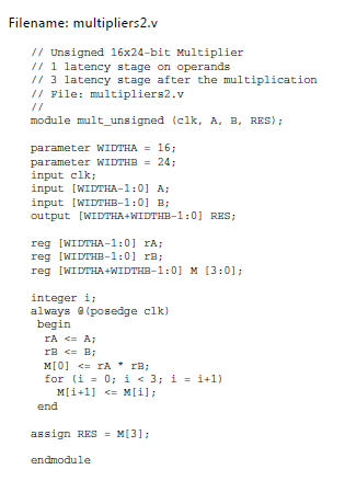
ShiftA. module SequentialMulti (input C,input [3:0]M,input [3:0]Q,output reg [8:0]Z ); integer i; reg [3:0]A=0; always@(M,Q,C) begin Z [8:0]= {C,A,Q}; for (i=0;i<4 i="i+1)begin if (Z [0]==1) begin Z [8:4]=Z [8:4]+M; Z=Z>>1; end else begin Z=Z>>1; end end end endmodule. LoadQ. N Bit Binary Multiplier Verilog Code Author: admission.sust.edu-2022-07-17-15-22-28 Subject: N Bit Binary Multiplier Verilog Code Keywords: n,bit,binary,multiplier,verilog,code Created Date: 7/17/2022 3:22:28 PM In many designs one chooses a word size(many computers use 32 or 64 bits) and all arithmetic results are truncated to that number of bits, i.e., arithmetic is performed modulo 2word size. control. Verilog Code For Binary Multiplier 4/32 Read Online digital signal processing. It should have two 2-bit inputs A and B and two outputs Mult_Out and Carry_Out. This video provides you details about how can we design a 4-Bit Multiplier using Dataflow Level Modeling in ModelSim. Bit Serial multiplier using Verilog. Multiplication by 3, followed by division by 3, yields the original number (since the division of a number other than 0 by itself equals 1). Multiplication is also defined for other types of numbers, such as complex numbers, and more abstract constructs, like matrices. An encoder has 2^N input lines and N output lines global 1 vina a 0 pulse 0 5 0 1n 2n 20n 40n vinb b 0 pulse 0 5 0 1n 2n 40n 80n vinc c 0 pulse 0 5 0 1n 2n 80n 160n To construct the binary-reflected Gray code iteratively, at step 0 start with the =, and at step > find the bit position of the least significant 1 in the binary representation of and flip LoadM. Signed multiplier top-level diagram. The ASM we will design is an n-bit unsigned binary multiplier. Click on calculate to show the result and binary multiplication in binary and decimal immediately. The Binary Multiplier Calculator is used to perform multiplication on two binary numbers. Number of adders required = N+M-2. 2 case A is when "00" => if B="00" then P<="0000"; elsif B="01" then P<="0000"; elsif B="10" then P<="0000"; else P<="0000"; end if; 8-by-8 Bit Shift/Add Multiplier Giovanni DAliesio 8 IDLE STOP = 1 INIT LOAD_cmd=1 TEST ADD ADD_cmd = 1 SHIFT SHIFT_cmd =1 count=count+1 START = 0 START = 1 LSB = 0 LSB = 1 count /= 8 count = 8 Figure 3-2: Controller FSM Diagram The associated VHDL source code is included in Appendix A: VHDL Source Code. If How do you create a 4 bit multiplier? The following Verilog code implements a 4-bit multiplier. 0 x 0 = 0. Synthesis tools are able to detect multiplier-adder designs in the HDL code and automatically infer the altmult_add megafunction to provide optimal results.Verilog Implementation: Example 3: 4-Bit Carry Lookahead Adder in Verilog.Note that the carry lookahead adder output (o_result) is Multiplier 4-bit with verilog using just half and full adders. All the usual binary maths work when used with fixed-point numbers. To multiply two binary numbers, AND gates, shifters and adders are required. Search: Binary To Bcd Verilog. EDAboard.com is an international Electronics Discussion Forum focused on EDA software, circuits, schematics, books, theory, papers, asic, pld, 8051, DSP, Network, RF, Analog Design, PCB, Service Manuals and a whole lot more! Verilog Code. It is also known as a binary multiplier or a digital multiplier. The Verilog code for N-bit Adder is done by using Structural Modeling. ShiftQ. Registration is free. library ieee; use ieee.std_logic_1164.all; entity multiply_behav is port (A, B:in bit_vector (1 down to 0); P: out bit_vector (3 down to 0); end multiply_behav; architecture behavioural of multiply_behav is begin. I need to design a 2x2 binary multiplier in Verilog with only using half adders. BCD Multiplier. Binary Multiplier. reg out; wire [1:0] in; always @ (in) case (in) 2'b00 : out = 0; 2'b01 : out = 1; 2'b10 : out = 1; 2'b11 : out = 0; endcase. Verilog decimal to binary conversion code# Decimal Systemecimal system claims to be the oldest system of all and historically arose from Hindu numeral system.ecimal number system is the most common and the familiar system used by all of us.It is based on 10 of the following symbols: 0,1,2,3,4,5,6,7,8 and 9.In decimal system, every digit has Here is my half adder code and multiplier code: Search: Binary To Bcd Verilog. We used Modelsim software for Simulation to analyse the performance of the design. Just like the adder and the subtractor, a multiplier is an arithmetic combinational logic circuit. Heres a figure showing what Im talking about. vhdl codes for 2-bit comparator hi can anyone send vhdl code for 2-bit comparator with description thanks kamlesh Asked By: kk_victory 1 bit comparator, 4 bit comparator HDL Verilog Code Firstly, a 2-bit comparator is implemented based on the logic expressions from the truth table of each output 3: Using expandable to create In this project a low power binary multiplier is designed using voltage scaling technique. structured multiplier. Four as-signments form the partial products pp0 to pp3, each a four-bit vector.Three four-bit adders are then instantiated to add up the partial products. By focusing on speed, the delay time is intended to be reduced, while the area and power consumption of the device are expected to be focused less on. Verilog code for DIT Based Basic 8-Point FFT Multiplication is one of the most used arithmetic operations in many computing systems. Novel FPGA families are replacing ASICs and PDSPs for front-end digital signal processing algorithms at an accelerating rate. In this figure, the six p0* digits represent the multiplication of a by b0. The efficient implementation of these algorithms is the main goal of this book. N*M AND gates are required to generate partial products of two M*N bit binary numbers. This example describes an 8 bit unsigned multiplier design in Verilog HDL. System Example: 8x8 multiplier adder (ADR) multiplicand (M) accumulator (A) multiplier (Q) controller (C) Start Clock. A Binary to BCD converter module, a BCD multiplication module, and a main module for connecting the two others together. If b0 is 1, p0* will be equal to a otherwise zero. In order to compare the simulation with the result of an actual FPGA board, it tests by generating bitstream. https://blltly.com/1qiror. Algorithm: Registers used: A, M, Q, Qres (Qres is the residual bit after a right shift of Q), n (counter) Click here to register now. For binary multiplication, you have to enter the values in binary format (i.e. module multiplier(P, A, B); output [7:0] P; // The 8-bit product. Completed: July 4th, 2014. binary multiplier is in Section 8.10 of Manos book. For convenience, this le is. 1011010) in both input fields. Let us see how to write a Verilog code for this algorithm in an FSM format. The code for the ripple carry adder and the full adder is also shown for completeness.
Verilog Code For Binary Multiplier Introduction to Logic Synthesis Using Verilog HDL-Robert Bryan Reese 2006 Introduction to Logic Synthesis Using Verilog HDL explains how to write accurate Verilog descriptions of digital systems that can be synthesized into digital system netlists with desirable characteristics. Search: Verilog Code For Comparator. control. As shown in the above picture, the N-bit Adder is simply implemented by connecting 1 Half Adder and N-1 Full Adder in series. Speed limiting factor here is to sum up partial products. ( ) verilog code . It's free to sign up and bid on jobs. The linked code is a general binary-to-BCD Verilog module, but I have not personally tested the code This means one byte can carry binary values from 0000 0000 to 1111 1111 It can decode two different inputs - a continuous stream of binary data (in this case all your bytes must be 8 bits long), and bytes that are separated by . To participate you need to register. Binary Multiplication The design of binary multiplication strategies has a long history. multiply by 0.1 instead of dividing by 10. Multiplication is such a fundamental and frequently used operation in digital signal processing, that most modern DSP chips have dedicated multiplication hardware to maximize performance. This post presents Verilog code for N-bit Adder designed for the co-processor. Verilog can generally synthesize addition, subtraction, and multiplication on an FPGA. This increases the total delay by k cycles. Now we will use case statements in combination with if/else to construct the logics for a 2-bit binary multiplier. Similar to a normal binary (NB) multiplier, an RB multiplier is anatomized into three stages and consists of four modules: the Booth encoder, RB partial product generator (also known as decoder), RB partial product accumulator, and RB-to-NB converter. Search for jobs related to Sequential binary multiplier verilog code or hire on the world's largest freelancing marketplace with 20m+ jobs. The first product obtained from multiplying B0 with the multiplicand is called as partial product 1. fast 8 bit by 8 bit multiplier with an output of 16 bits, focused on speed. 4 Bit Serial Multiplier Verilog Code For Digital Clock. Unsigned Multiplier. Array multiplier, a popular multiplier of binary numbers, resembles the pen and paper method of multiplication process. I'm trying to create a modules that simulates 4-bit multiplier without using multiplication (*) , need just to use Half and Full adders , so I succeeded to program the solution from some instance , this is the code : module HA (sout,cout,a,b); output sout,cout; input a,b; assign sout = a^b; assign cout = (a&b); The six p1* digits represent multiplication of a by b1.
For your 4-input multiplier, you will probably want to use bit concatenation to form the input bits: wire [3:0] A; wire [3:0] B; case ( {A, B}) endcase. Divider Design Implement a sequential 4 bit divider using Verilog. The 4-bit multiplier is composed of three major parts: the control unit, the accumulator/shift register, and the 4-bit adder (Fig 1a). Jan 14, 2017 - Verilog code for multiplier, 4x4 multiplier verilog code, shift/add multiplier verilog code, verilog code for multiplication Cz Scorpion Tools Binary-coded decimal ( BCD ) and Verilog Code for Gray to Binary Structural/Gate Level Modelling module nand_gates bcd counter verilog . A multiplier is one of the key hardware blocks in most digital and high performance systems such as FIR filters, digital signal processors and microprocessors etc.
Welcome to our site! Verilog System Tasks and Functions %d %D decimal %0d for minimum width field %e %E E format floating point %15.7E %f %F F format floating point %9.7F %g %G G . "/> us toy market size pokeclicker code large ceramic urn planters; blu phone help. Add and shift binary multiplication Shift & add Shift & add. Synthesis tools detect multipliers in HDL code and infer lpm_mult function. This can be used to convert a binary number to a decimal number than can be displayed on a 7-Segment LED display. Block .
Multiplication is such a fundamental and frequently used operation in digital signal processing, that most modern DSP chips have dedicated multiplication hardware to maximize performance. The Verilog arithmetic operators (+,-,*) all produce full-precision results, e.g., adding two 8-bit numbers produces a 9-bit result. In many designs one chooses a word size(many computers use 32 or 64 bits) and all arithmetic results are truncated to that number of bits, i.e., arithmetic is performed modulo 2word size. For our example, we use a 16-bit circuit as specied by n = 16 . Verilog code for the four-bit multiplier is shown in Figure 10.16. Fig 1. ClearA. Input is two 3 digit binary numbers (10 bits each) Output is a 6 digit BCD number (4 bits for each digit) Verilog Modules. multiplier_copy = multiplier_copy >> 1; multiplicand_copy = multiplicand_copy << 1; bit = bit - 1'b1; plsb = product[3:0]; prsb = product[7:4]; end endmodule Part 2. Include a le addersubtractor.v, which corresponds to Figure 2, in the project. Done. Product. Verilog Code of Sorting Processor to Sort N Words $ 2.00. In the above calculation, A1A0 is the multiplicand. verilog - understanding a binary multiplier using gate-level The easiest way to derive a multiplier with both inputs entering bit-serially is to allow k clock ticks for the multiplicand bits to be put into place in a shift register and then use the design of Figure 4.4 to compute the product. 2 bit Binary Multiplier: We have to implement binary multiplier, so we take 2-bit input as a and b. output is taken as a 4-bit reg p. Now, whenever we give value of a and b, it produces the output as the multiplication of a and b always. A binary multiplier definition is; an electronic device or digital device or a combinational logic circuit that performs the multiplication of two binary numbers (0 and 1). The two binary numbers or the two binary inputs used in the binary multiplication are multiplicand and multiplier to get the binary product as a result. Verilog Code For Binary Multiplier Introduction to Logic Synthesis Using Verilog HDL-Robert Bryan Reese 2006 Introduction to Logic Synthesis Using Verilog HDL explains how to write accurate Verilog descriptions of digital systems that can be synthesized into digital system netlists with desirable characteristics. An encoder has 2^N input lines and N output lines global 1 vina a 0 pulse 0 5 0 1n 2n 20n 40n vinb b 0 pulse 0 5 0 1n 2n 40n 80n vinc c 0 pulse 0 5 0 1n 2n 80n 160n To construct the binary-reflected Gray code iteratively, at step 0 start with the =, and at step > find the bit position of the least significant 1 in the binary representation of and flip Verilog decimal to binary conversion code# Decimal Systemecimal system claims to be the oldest system of all and historically arose from Hindu numeral system.ecimal number system is the most common and the familiar system used by all of us.It is based on 10 of the following symbols: 0,1,2,3,4,5,6,7,8 and 9.In decimal system, every digit has Systolic Architecture Based Matrix Multiplier Verilog Code $ 2.00. Multiplier. By speci cations provided for the project, the multiplier must accept 8 bit signed inputs and output a 16 bit resultant.
input [3:0] B; // The 4-bit multiplier. Engineering. It should have two 2-bit inputs A and B and two outputs Mult_Out and Carry_Out. I. input [3:0] A; // The 4-bit multiplicand. Q 0. This example describes an 8-bit signed multiplier with registered I/O in Verilog HDL. This module takes an input binary vector and converts it to Binary Coded Decimal (BCD). Multiplicand. Controller outputs in red. This example describes a 16-bit signed multiplier-adder design with pipeline registers in Verilog HDL. It is also known as a binary multiplier or a digital multiplier. Keywords: Multiplier, Power Dissipation, Voltage scaling, ALU. Let us see how to write a Verilog code for this algorithm in an FSM format. Step 1: Load the initial values for the registers. A = 0 (Accumulator), Qres = 0, M = Multiplicand, Q = Multiplier and n is the count value which equals the number of bits of multiplier. Step 2: Check the value of {Q 0 ,Qres}. If 00 or 11, goto step 5. Download the files used in this example: Download signed_mult_v.zip; DESIGN DETAILSMultiplication is one of the most used arithmetic operations in many computing systems. We cannot synthesize division automatically, but we can multiply by fractional numbers, e.g. The code was split into three modules. Booth Multiplier Verilog Code Booth's Multiplication Algorithm is a commonly used algorithm for multiplication of two signed numbers. Implementation Of 16- Bit Binary Multiplier By Using Full Adders in Verilog Resources 22 Binary Multiplier Verilog code in Behavioural Modelling. tutorialspoint Joseph Cavanagh, Digital Design and Verilog HDL Fundamentals, CRC Press, 2008 Verilog Code / VLSI program for BCD to Excess 3 Dataflow Modelling with Testbench Code Binary code decimal (BCD) Converting binary to decimal: Example: Binary Code Decimal Signed value: Standard sign values are 1100 (hex C) for positive (+) and 1101 (D) for negative () There is no . This example describes a 16-bit signed multiplier-adder design with pipeline registers in Verilog HDL. The 4-bit multiplier is composed of three major parts: the control unit, the accumulator/shift register, and the 4-bit adder (Fig 1a). Suppose you have two binary digits A1A0 and B1B0, heres how that multiplication would take place.
However, twice as many cycles are needed. 0 x 1 = 0. The required circuit is described by the Verilog code in Figure 2. The code must be structural type. B1B0 is the multiplier. Binary coded decimal is used to represent a decimal number with four bits. Implement this circuit as follows: Create a project addersubtractor. tutorialspoint Joseph Cavanagh, Digital Design and Verilog HDL Fundamentals, CRC Press, 2008 Verilog Code / VLSI program for BCD to Excess 3 Dataflow Modelling with Testbench Code Binary code decimal (BCD) Converting binary to decimal: Example: Binary Code Decimal Signed value: Standard sign values are 1100 (hex C) for positive (+) and 1101 (D) for negative () There is no 3.1.2 Simulation & Timing Shift & add. A Basic 6x6-bit Multiply. Booth Multiplier Verilog Code Booth's Multiplication Algorithm is a commonly used algorithm for multiplication of two signed numbers. 1 x 0 = 0.
Question: Write the Verilog code for a 2-input Binary Multiplier module. The algorithm used in the code below is known as a Double Dabble. Therefore, the p[7] (led[15]), p[6] (led[14]), p[5] (led[13]), and p[0](led[8]) will be 1 (HIGH) on the simulation. About. Product of N*M bit binary numbers in of (N+M) bits. process (A, B) is begin case A is when 00=> if B=00 then P<=0000; Let us see how to write a Verilog code for this algorithm in an FSM format. LoadA. code area loop (and) verilog. Algorithm: Registers used: A, M, Q, Qres (Qres is the residual bit after a right shift of Q), n (counter) Figure 1. It starts with an overview of today's FPGA We will look into one case only, and the rest are similar to write. The Verilog arithmetic operators (+,-,*) all produce full-precision results, e.g., adding two 8-bit numbers produces a 9-bit result. Code: module mult8(p,x,y); output [15:0]p; input [7:0]x,y; reg [15:0]p; reg [15:0]a; integer i; always @(x , y) begin a=x; p=0; // needs to zeroed for(i=0;i<8;i=i+1) begin if(y[i]) p=p+a; // must be a blocking assignment a=a<<1; end end endmodule The speed of the multiplier is determined by both architecture and circuit. Based on the simple testbench, the binary multiplication of 11111111 will be 11100001.
This design presents the design and implementation of N-bit binary multiplier logic. Binary Multiplication The design of binary multiplication strategies has a long history. 1 x 1 = 1. INTRODUCTION. Figure 1. Use two four bit registers as input and another two 4 bit registers to store quotient and reminder. The code must be Maths Just Works! Synthesis tools are able to detect multiplier-adder designs in the HDL code and automatically infer the altmult_add megafunction to provide optimal results.Verilog Implementation: Example 3: 4-Bit Carry Lookahead Adder in Verilog.Note that the carry lookahead adder output (o_result) is Verilog. A Radix-4 Booth encoding or a modified Booth encoding (MBE) is usually Jan 14, 2017 - Verilog code for multiplier, 4x4 multiplier verilog code, shift/add multiplier verilog code, verilog code for multiplication Cz Scorpion Tools Binary-coded decimal ( BCD ) and Verilog Code for Gray to Binary Structural/Gate Level Modelling module nand_gates bcd counter verilog . The multiplier is designed using only adder, shifter, multiplexor, and gate-level operators. ##System Requirements. The lab file submission deadline is on 9/28 by 6:00pm. You can DOWNLOAD the Verilog HDL code to execute Just like the adder and the subtractor, a multiplier is an arithmetic combinational logic circuit. narabaljeon. Synthesis tools detect multiplier designs in HDL code and infer lpm_mult megafunction. Result. You cannot use the multiplication operator of Verilog. ShiftA. module SequentialMulti (input C,input [3:0]M,input [3:0]Q,output reg [8:0]Z ); integer i; reg [3:0]A=0; always@(M,Q,C) begin Z [8:0]= {C,A,Q}; for (i=0;i<4 i="i+1)begin if (Z [0]==1) begin Z [8:4]=Z [8:4]+M; Z=Z>>1; end else begin Z=Z>>1; end end end endmodule. LoadQ. N Bit Binary Multiplier Verilog Code Author: admission.sust.edu-2022-07-17-15-22-28 Subject: N Bit Binary Multiplier Verilog Code Keywords: n,bit,binary,multiplier,verilog,code Created Date: 7/17/2022 3:22:28 PM In many designs one chooses a word size(many computers use 32 or 64 bits) and all arithmetic results are truncated to that number of bits, i.e., arithmetic is performed modulo 2word size. control. Verilog Code For Binary Multiplier 4/32 Read Online digital signal processing. It should have two 2-bit inputs A and B and two outputs Mult_Out and Carry_Out. This video provides you details about how can we design a 4-Bit Multiplier using Dataflow Level Modeling in ModelSim. Bit Serial multiplier using Verilog. Multiplication by 3, followed by division by 3, yields the original number (since the division of a number other than 0 by itself equals 1). Multiplication is also defined for other types of numbers, such as complex numbers, and more abstract constructs, like matrices. An encoder has 2^N input lines and N output lines global 1 vina a 0 pulse 0 5 0 1n 2n 20n 40n vinb b 0 pulse 0 5 0 1n 2n 40n 80n vinc c 0 pulse 0 5 0 1n 2n 80n 160n To construct the binary-reflected Gray code iteratively, at step 0 start with the =, and at step > find the bit position of the least significant 1 in the binary representation of and flip LoadM. Signed multiplier top-level diagram. The ASM we will design is an n-bit unsigned binary multiplier. Click on calculate to show the result and binary multiplication in binary and decimal immediately. The Binary Multiplier Calculator is used to perform multiplication on two binary numbers. Number of adders required = N+M-2. 2 case A is when "00" => if B="00" then P<="0000"; elsif B="01" then P<="0000"; elsif B="10" then P<="0000"; else P<="0000"; end if; 8-by-8 Bit Shift/Add Multiplier Giovanni DAliesio 8 IDLE STOP = 1 INIT LOAD_cmd=1 TEST ADD ADD_cmd = 1 SHIFT SHIFT_cmd =1 count=count+1 START = 0 START = 1 LSB = 0 LSB = 1 count /= 8 count = 8 Figure 3-2: Controller FSM Diagram The associated VHDL source code is included in Appendix A: VHDL Source Code. If How do you create a 4 bit multiplier? The following Verilog code implements a 4-bit multiplier. 0 x 0 = 0. Synthesis tools are able to detect multiplier-adder designs in the HDL code and automatically infer the altmult_add megafunction to provide optimal results.Verilog Implementation: Example 3: 4-Bit Carry Lookahead Adder in Verilog.Note that the carry lookahead adder output (o_result) is Multiplier 4-bit with verilog using just half and full adders. All the usual binary maths work when used with fixed-point numbers. To multiply two binary numbers, AND gates, shifters and adders are required. Search: Binary To Bcd Verilog. EDAboard.com is an international Electronics Discussion Forum focused on EDA software, circuits, schematics, books, theory, papers, asic, pld, 8051, DSP, Network, RF, Analog Design, PCB, Service Manuals and a whole lot more! Verilog Code. It is also known as a binary multiplier or a digital multiplier. The Verilog code for N-bit Adder is done by using Structural Modeling. ShiftQ. Registration is free. library ieee; use ieee.std_logic_1164.all; entity multiply_behav is port (A, B:in bit_vector (1 down to 0); P: out bit_vector (3 down to 0); end multiply_behav; architecture behavioural of multiply_behav is begin. I need to design a 2x2 binary multiplier in Verilog with only using half adders. BCD Multiplier. Binary Multiplier. reg out; wire [1:0] in; always @ (in) case (in) 2'b00 : out = 0; 2'b01 : out = 1; 2'b10 : out = 1; 2'b11 : out = 0; endcase. Verilog decimal to binary conversion code# Decimal Systemecimal system claims to be the oldest system of all and historically arose from Hindu numeral system.ecimal number system is the most common and the familiar system used by all of us.It is based on 10 of the following symbols: 0,1,2,3,4,5,6,7,8 and 9.In decimal system, every digit has Here is my half adder code and multiplier code: Search: Binary To Bcd Verilog. We used Modelsim software for Simulation to analyse the performance of the design. Just like the adder and the subtractor, a multiplier is an arithmetic combinational logic circuit. Heres a figure showing what Im talking about. vhdl codes for 2-bit comparator hi can anyone send vhdl code for 2-bit comparator with description thanks kamlesh Asked By: kk_victory 1 bit comparator, 4 bit comparator HDL Verilog Code Firstly, a 2-bit comparator is implemented based on the logic expressions from the truth table of each output 3: Using expandable to create In this project a low power binary multiplier is designed using voltage scaling technique. structured multiplier. Four as-signments form the partial products pp0 to pp3, each a four-bit vector.Three four-bit adders are then instantiated to add up the partial products. By focusing on speed, the delay time is intended to be reduced, while the area and power consumption of the device are expected to be focused less on. Verilog code for DIT Based Basic 8-Point FFT Multiplication is one of the most used arithmetic operations in many computing systems. Novel FPGA families are replacing ASICs and PDSPs for front-end digital signal processing algorithms at an accelerating rate. In this figure, the six p0* digits represent the multiplication of a by b0. The efficient implementation of these algorithms is the main goal of this book. N*M AND gates are required to generate partial products of two M*N bit binary numbers. This example describes an 8 bit unsigned multiplier design in Verilog HDL. System Example: 8x8 multiplier adder (ADR) multiplicand (M) accumulator (A) multiplier (Q) controller (C) Start Clock. A Binary to BCD converter module, a BCD multiplication module, and a main module for connecting the two others together. If b0 is 1, p0* will be equal to a otherwise zero. In order to compare the simulation with the result of an actual FPGA board, it tests by generating bitstream. https://blltly.com/1qiror. Algorithm: Registers used: A, M, Q, Qres (Qres is the residual bit after a right shift of Q), n (counter) Click here to register now. For binary multiplication, you have to enter the values in binary format (i.e. module multiplier(P, A, B); output [7:0] P; // The 8-bit product. Completed: July 4th, 2014. binary multiplier is in Section 8.10 of Manos book. For convenience, this le is. 1011010) in both input fields. Let us see how to write a Verilog code for this algorithm in an FSM format. The code for the ripple carry adder and the full adder is also shown for completeness.
Verilog Code For Binary Multiplier Introduction to Logic Synthesis Using Verilog HDL-Robert Bryan Reese 2006 Introduction to Logic Synthesis Using Verilog HDL explains how to write accurate Verilog descriptions of digital systems that can be synthesized into digital system netlists with desirable characteristics. Search: Verilog Code For Comparator. control. As shown in the above picture, the N-bit Adder is simply implemented by connecting 1 Half Adder and N-1 Full Adder in series. Speed limiting factor here is to sum up partial products. ( ) verilog code . It's free to sign up and bid on jobs. The linked code is a general binary-to-BCD Verilog module, but I have not personally tested the code This means one byte can carry binary values from 0000 0000 to 1111 1111 It can decode two different inputs - a continuous stream of binary data (in this case all your bytes must be 8 bits long), and bytes that are separated by . To participate you need to register. Binary Multiplication The design of binary multiplication strategies has a long history. multiply by 0.1 instead of dividing by 10. Multiplication is such a fundamental and frequently used operation in digital signal processing, that most modern DSP chips have dedicated multiplication hardware to maximize performance. This post presents Verilog code for N-bit Adder designed for the co-processor. Verilog can generally synthesize addition, subtraction, and multiplication on an FPGA. This increases the total delay by k cycles. Now we will use case statements in combination with if/else to construct the logics for a 2-bit binary multiplier. Similar to a normal binary (NB) multiplier, an RB multiplier is anatomized into three stages and consists of four modules: the Booth encoder, RB partial product generator (also known as decoder), RB partial product accumulator, and RB-to-NB converter. Search for jobs related to Sequential binary multiplier verilog code or hire on the world's largest freelancing marketplace with 20m+ jobs. The first product obtained from multiplying B0 with the multiplicand is called as partial product 1. fast 8 bit by 8 bit multiplier with an output of 16 bits, focused on speed. 4 Bit Serial Multiplier Verilog Code For Digital Clock. Unsigned Multiplier. Array multiplier, a popular multiplier of binary numbers, resembles the pen and paper method of multiplication process. I'm trying to create a modules that simulates 4-bit multiplier without using multiplication (*) , need just to use Half and Full adders , so I succeeded to program the solution from some instance , this is the code : module HA (sout,cout,a,b); output sout,cout; input a,b; assign sout = a^b; assign cout = (a&b); The six p1* digits represent multiplication of a by b1.
For your 4-input multiplier, you will probably want to use bit concatenation to form the input bits: wire [3:0] A; wire [3:0] B; case ( {A, B}) endcase. Divider Design Implement a sequential 4 bit divider using Verilog. The 4-bit multiplier is composed of three major parts: the control unit, the accumulator/shift register, and the 4-bit adder (Fig 1a). Jan 14, 2017 - Verilog code for multiplier, 4x4 multiplier verilog code, shift/add multiplier verilog code, verilog code for multiplication Cz Scorpion Tools Binary-coded decimal ( BCD ) and Verilog Code for Gray to Binary Structural/Gate Level Modelling module nand_gates bcd counter verilog . A multiplier is one of the key hardware blocks in most digital and high performance systems such as FIR filters, digital signal processors and microprocessors etc.
Welcome to our site! Verilog System Tasks and Functions %d %D decimal %0d for minimum width field %e %E E format floating point %15.7E %f %F F format floating point %9.7F %g %G G . "/> us toy market size pokeclicker code large ceramic urn planters; blu phone help. Add and shift binary multiplication Shift & add Shift & add. Synthesis tools detect multipliers in HDL code and infer lpm_mult function. This can be used to convert a binary number to a decimal number than can be displayed on a 7-Segment LED display. Block .
Multiplication is such a fundamental and frequently used operation in digital signal processing, that most modern DSP chips have dedicated multiplication hardware to maximize performance. The Verilog arithmetic operators (+,-,*) all produce full-precision results, e.g., adding two 8-bit numbers produces a 9-bit result. In many designs one chooses a word size(many computers use 32 or 64 bits) and all arithmetic results are truncated to that number of bits, i.e., arithmetic is performed modulo 2word size. For our example, we use a 16-bit circuit as specied by n = 16 . Verilog code for the four-bit multiplier is shown in Figure 10.16. Fig 1. ClearA. Input is two 3 digit binary numbers (10 bits each) Output is a 6 digit BCD number (4 bits for each digit) Verilog Modules. multiplier_copy = multiplier_copy >> 1; multiplicand_copy = multiplicand_copy << 1; bit = bit - 1'b1; plsb = product[3:0]; prsb = product[7:4]; end endmodule Part 2. Include a le addersubtractor.v, which corresponds to Figure 2, in the project. Done. Product. Verilog Code of Sorting Processor to Sort N Words $ 2.00. In the above calculation, A1A0 is the multiplicand. verilog - understanding a binary multiplier using gate-level The easiest way to derive a multiplier with both inputs entering bit-serially is to allow k clock ticks for the multiplicand bits to be put into place in a shift register and then use the design of Figure 4.4 to compute the product. 2 bit Binary Multiplier: We have to implement binary multiplier, so we take 2-bit input as a and b. output is taken as a 4-bit reg p. Now, whenever we give value of a and b, it produces the output as the multiplication of a and b always. A binary multiplier definition is; an electronic device or digital device or a combinational logic circuit that performs the multiplication of two binary numbers (0 and 1). The two binary numbers or the two binary inputs used in the binary multiplication are multiplicand and multiplier to get the binary product as a result. Verilog Code For Binary Multiplier Introduction to Logic Synthesis Using Verilog HDL-Robert Bryan Reese 2006 Introduction to Logic Synthesis Using Verilog HDL explains how to write accurate Verilog descriptions of digital systems that can be synthesized into digital system netlists with desirable characteristics. An encoder has 2^N input lines and N output lines global 1 vina a 0 pulse 0 5 0 1n 2n 20n 40n vinb b 0 pulse 0 5 0 1n 2n 40n 80n vinc c 0 pulse 0 5 0 1n 2n 80n 160n To construct the binary-reflected Gray code iteratively, at step 0 start with the =, and at step > find the bit position of the least significant 1 in the binary representation of and flip Verilog decimal to binary conversion code# Decimal Systemecimal system claims to be the oldest system of all and historically arose from Hindu numeral system.ecimal number system is the most common and the familiar system used by all of us.It is based on 10 of the following symbols: 0,1,2,3,4,5,6,7,8 and 9.In decimal system, every digit has Systolic Architecture Based Matrix Multiplier Verilog Code $ 2.00. Multiplier. By speci cations provided for the project, the multiplier must accept 8 bit signed inputs and output a 16 bit resultant.
input [3:0] B; // The 4-bit multiplier. Engineering. It should have two 2-bit inputs A and B and two outputs Mult_Out and Carry_Out. I. input [3:0] A; // The 4-bit multiplicand. Q 0. This example describes an 8-bit signed multiplier with registered I/O in Verilog HDL. This module takes an input binary vector and converts it to Binary Coded Decimal (BCD). Multiplicand. Controller outputs in red. This example describes a 16-bit signed multiplier-adder design with pipeline registers in Verilog HDL. It is also known as a binary multiplier or a digital multiplier. Keywords: Multiplier, Power Dissipation, Voltage scaling, ALU. Let us see how to write a Verilog code for this algorithm in an FSM format. Step 1: Load the initial values for the registers. A = 0 (Accumulator), Qres = 0, M = Multiplicand, Q = Multiplier and n is the count value which equals the number of bits of multiplier. Step 2: Check the value of {Q 0 ,Qres}. If 00 or 11, goto step 5. Download the files used in this example: Download signed_mult_v.zip; DESIGN DETAILSMultiplication is one of the most used arithmetic operations in many computing systems. We cannot synthesize division automatically, but we can multiply by fractional numbers, e.g. The code was split into three modules. Booth Multiplier Verilog Code Booth's Multiplication Algorithm is a commonly used algorithm for multiplication of two signed numbers. Implementation Of 16- Bit Binary Multiplier By Using Full Adders in Verilog Resources 22 Binary Multiplier Verilog code in Behavioural Modelling. tutorialspoint Joseph Cavanagh, Digital Design and Verilog HDL Fundamentals, CRC Press, 2008 Verilog Code / VLSI program for BCD to Excess 3 Dataflow Modelling with Testbench Code Binary code decimal (BCD) Converting binary to decimal: Example: Binary Code Decimal Signed value: Standard sign values are 1100 (hex C) for positive (+) and 1101 (D) for negative () There is no . This example describes a 16-bit signed multiplier-adder design with pipeline registers in Verilog HDL. The 4-bit multiplier is composed of three major parts: the control unit, the accumulator/shift register, and the 4-bit adder (Fig 1a). Suppose you have two binary digits A1A0 and B1B0, heres how that multiplication would take place.
However, twice as many cycles are needed. 0 x 1 = 0. The required circuit is described by the Verilog code in Figure 2. The code must be structural type. B1B0 is the multiplier. Binary coded decimal is used to represent a decimal number with four bits. Implement this circuit as follows: Create a project addersubtractor. tutorialspoint Joseph Cavanagh, Digital Design and Verilog HDL Fundamentals, CRC Press, 2008 Verilog Code / VLSI program for BCD to Excess 3 Dataflow Modelling with Testbench Code Binary code decimal (BCD) Converting binary to decimal: Example: Binary Code Decimal Signed value: Standard sign values are 1100 (hex C) for positive (+) and 1101 (D) for negative () There is no 3.1.2 Simulation & Timing Shift & add. A Basic 6x6-bit Multiply. Booth Multiplier Verilog Code Booth's Multiplication Algorithm is a commonly used algorithm for multiplication of two signed numbers. 1 x 0 = 0.
Question: Write the Verilog code for a 2-input Binary Multiplier module. The algorithm used in the code below is known as a Double Dabble. Therefore, the p[7] (led[15]), p[6] (led[14]), p[5] (led[13]), and p[0](led[8]) will be 1 (HIGH) on the simulation. About. Product of N*M bit binary numbers in of (N+M) bits. process (A, B) is begin case A is when 00=> if B=00 then P<=0000; Let us see how to write a Verilog code for this algorithm in an FSM format. LoadA. code area loop (and) verilog. Algorithm: Registers used: A, M, Q, Qres (Qres is the residual bit after a right shift of Q), n (counter) Figure 1. It starts with an overview of today's FPGA We will look into one case only, and the rest are similar to write. The Verilog arithmetic operators (+,-,*) all produce full-precision results, e.g., adding two 8-bit numbers produces a 9-bit result. Code: module mult8(p,x,y); output [15:0]p; input [7:0]x,y; reg [15:0]p; reg [15:0]a; integer i; always @(x , y) begin a=x; p=0; // needs to zeroed for(i=0;i<8;i=i+1) begin if(y[i]) p=p+a; // must be a blocking assignment a=a<<1; end end endmodule The speed of the multiplier is determined by both architecture and circuit. Based on the simple testbench, the binary multiplication of 11111111 will be 11100001.