We will use the same functions here as well to draw the clock face. Craig Lindley Otherwise, the clock wont be able to access the Internet, and by extension the NTP servers that provide the time. If your IDE does not have the plugins installed you can visit the links below: Installing ESP32 library in Arduino IDE and upload code. Moreover, we will add a delay of 1 second after which the loop() will run again so that the clock updates every second. Then we will print the individual hour , minute and second in the serial monitor in a format HH:MM:SS. We will upload a program code in our ESP32/ESP8266 board using Arduino IDE which will connect to the NTP server through our local network and we will request the current time. The project libraries are used to set up the Wi-Fi and receive time from NTP servers. }.  udp.beginPacket(address, 123); // NTP requests are to port 123
utcOffsetInSeconds is a UTC offset time, You can find your own country or regions UTC offset time. it shows up at the esp.restart(). First and most importantly you must modify the code with the SSID and password of your Wi-Fi network. If you havent setup your Arduino IDE for ESP8266, First of all set up Arduino IDE for ESP8266 and again come back to this project. You can download the code from below link. These clocks listen for WWV radio transmissions from Fort Collins, CO, and synchronize their time keeping mechanisms to the atomic clock reference used for these transmissions. Response);
According to Wikipedia: NTP is a networking protocol for clock synchronization between computer systems over packet-switched, variable-latency data networks. Pressing the DST button again toggles the clock out of DST mode. Next convert this angle to radians and then find the ending coordinates for the line that will represent the second hand. As daylight saving time comes and goes, the user will be required to inform the clock by pressing the DST pushbutton which toggles this mode on and off. esp8266 ntp timezone instructables
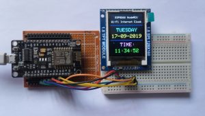
This clock has a single pushbutton switch that if configured for daylight saving time operation (more on this later) allows the user to put the clock into and take the clock out of DST mode. The sun icon will be replaced by a moon icon after about 8 p.m. in the evening. First , we will clear the buffer then set the size of the text using setTextSize() and pass the size as a parameter inside it. These will hold our network credentials which will be used to connect to our wireless network. esp8266 clock ntp oled digital display using conclusion If there is no error in the serial monitor then after a few moments, the OLED will start displaying the Digital clock that will update after every second. All user configuration items are found in the ESP8266NTPClock.ino file. It is up to the user to set the clock to the correct time. After you have uploaded your code to the ESP32 or ESP8266 development board, press its ENABLE/RST button. PCs usually sync their RTC using an Internet standard called Network Time Protocol, or NTP. It is a standard Internet Protocol for synchronizing computer clocks with some specific NTP server over network. Now let us proceed towards the digital clock. First, we will create a tm structure called timeinfo that will be set to the localtime() function. Next convert this angle to radians and then find the ending coordinates for the line that will represent the minutes hand. NTP Digital Clock using ESP8266 and OLED Display, NodeMCU based WiFi Network Scanner with OLED Display, IoT Heart Rate Monitoring with ThingSpeak Platform, Temperature Monitoring with ESP-DASH Webserver, Wemos D1 Mini Web Server based Servo Motor Control, ESP8266 Web Server for Controlling Electrical Devices, Smart Switch using Blynk | IoT Based WiFi Switch, PIR based Motion Switch | PIR Sensor Light, IoT based water level Indicator using ESP8266, IoT Vehicle Parking System using ESP8266 and Blynk. Privacy Policy | NTP is a standard internet protocol that is widely used to synchronize computer clocks to a reference network. The first common solution to this challenge is to use RTC modules such as the DS1307, which are usually inaccurate. These are the centre coordinates of the OLED display. Subscribe to our blog to be the first one to view our content. About: #BnBe is a platform to help teach electronics no matter what the age or skill level. FIGURE 3. We learn how to build a cute little digital clock that communicates with NTP servers and displays network or internet time. After calling the libraries, we have to make changes from the following section, which is actually related to the Wi-Fi network used to receive data. Clocks like these typically require the user to select their time zone, but other than that do not offer any controls for manually setting the time. To use the OLED display in our project, we have to install the Adafruit SSD 1306 library and Adafruit GFX library in Arduino IDE. packetBuffer[43]; return secsSince1900 - 2208988800UL +
Main program. esp8266 clock simplest internet local oled instructables Copy the code given below in that file. So lets take a quick look at the code to see how it works. You must modify the following two variables with your network user information so that ESP8266 can communicate with the existing network. Now we have connected the NodeMCU board with OLED display as per the connection diagram and powered on the project. The wire by wire connections are shown in Table 1 (in case theyre not be clear from the Fritzing diagram). First, many ESP8266 modules can be purchased for under $10 in single unit quantities. clock ntp nodemcu esp8266 matrix digital circuit step components required Functions for sending UDP packets to NTP servers, and retrieving the GMT time and converting it to local time. oled clock esp8266 using iot ajax jpralves nodemcu arducam mini web camera If good quality components are used in the clock, time keeping accuracy can be pretty good. Before you can upload the sketch, make sure that you have installed the U8g2 library along with the board support package for the ESP8266 boards. For the Analog clock, we will first build the clock face, hour, minute, and second hands and accordingly acquire the time from the NTP server to display the Analog clock appropriately. One for the Analog clock and the other for the Digital clock. In this project, only two components are used, a nodemcu board with ESP8266 chip and an OLED display with ssd1306 chip. Remember, libraries must be installed in the arduino/libraries directory on your development computer and the Arduino IDE must be restarted to recognize them. 2 years ago. This protocol can be used to synchronize all network devices with synchronized global time (UTC) in a few milliseconds. Let us take a look at the OLED display which we will be using in this article. The ESP8266 NTP clock software is available at the article link; its called Lindley_ESP8266NTPClock.zip. To build this project, you will need a WeMos D1 mini or compatible board that uses the ESP8266 chipset along with an OLED module. FIGURE 4. If you are not sure how to upload the code then you can refer the guides below. esp8266 clock instructables Basing a digital clock design on NTP requires access to the Internet which can be expensive to implement, but allows for a very simple clock design for a couple of reasons. Whereas the hardware for this clock borders on the trivial, the software/firmware for the clock is a bit more involved and complex. This user guide is divided into the following sections: Our aim is to build two types of OLED based clocks: Analog and Digital using ESP32 and ESP8266 boards. If you are using the RESET pin then specify the GPIO through which you are connecting it with your development board. Therefore go to Tools > Board and select ESP32 Dev Module or NodeMCU 1.0. Similarly it goes for all the cities. Go to, Sketches Include Libraries Manage Libraries Search NTPClient Install. If you want to use any GPIO pins for I2C, you will have to set it in code using SoftI2C(). Misc functions for formatting the time data for display on the LCD. Set the cursor as well. Use the wiring diagram above to connect the OLED module to the microcontroller board. }
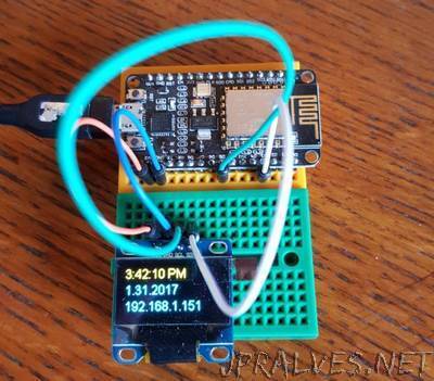
Initial Wi-Fi connection display. for New York UTC offset time is -4 Hour. See https://tools.ietf.org/html/rfc5905#section-7.3 for an explanation of the fields in the UDP request packet. #define WIFI_PASS xxxxxxxxxxxxx, #define TIMEZONE_OFFSET -7 // Set your timezone offset (-7 is mountain time)
But these chips are not quite accurate, so you have to make manual adjustments over and over again to make them synchronous. The NTP code in the file NTP.h is more complex, however. The first two parameters are the starting coordinates and the next two parameters are the ending coordinates of the line. packetBuffer[12] = 49;
Follow the schematic diagrams below for both the ESP modules and connect them accordingly. Likewise, we will multiply the radius with the cos(angle) then subtract it from 32 to get the starting y coordinate. Set HOUR_FORMAT_12 true to run your clock in 12 hour format; otherwise, it will operate in the 24 hour time format. Then, we will initialize the OLED display by creating an object of Adafruit_SSD1306 and specifying the width, height, I2C instance (&Wire), and -1 as parameters inside it. -1 specifies that the OLED display which we are using does not have a RESET pin. Inside our setup() function, we will initialize the serial communication at a baud rate of 112500. Figure 2 shows the design wired up and working on a breadboard. char daysOfTheWeek[7][4] = {"SUN", "MON", "TUE", "WED", "THU", "FRI", "SAT"}; NTPClient timeClient(ntpUDP, "pool.ntp.org", utcOffsetInSeconds); while ( WiFi.status() != WL_CONNECTED ) {, utcOffsetInSeconds = 5*60*60+60*30; // +5.5 UTC, utcOffsetInSeconds = 10*60*60; // +10 UTC, if (currentMillis - previousMillis >= interval) {. memset(packetBuffer, 0, NTP_PACKET_SIZE); // Initialize values needed to form NTP request
For this project, you dont need RTC Clock Module, Time will be updated from NTP. The getNTPTime function pulls this all together: // NTP Time Provider Code
To overcome the problems with manual time, date setting, and time drift, many so called atomic clocks or radio controlled clocks have appeared on the market. Its name shows that it is a flat light emitting technology that is developed when two organic thin films are connected in series between two electric conductors. We will first acquire the seconds from the tm structure by accessing tm_sec and update it to the floating variable called angle. This will save the time in seconds multiplied by 6. int size = udp.parsePacket();
If you are planning to supply power rather than USB, you need to supply separate 5v for LCD. The starting x and y coordinates of the line will be 64 and 32 respectively.
delay(4000);
Now we will display these same hour, min and second on the OLED display. NTP is intended to synchronize all participating computers to within a few milliseconds of Coordinated Universal Time (UTC). A time stamp packet contains several pieces of information such as date, time, accuracy, latency or time zone. By packetBuffer[0] = 0b11100011; // LI, Version, Mode
By default, the I2C pin in ESP32 for SDA is GPIO21, and for SCL is GPIO22. For detailed information, you can refer to the UTC time list. If clock power is lost, the connection to the Internet will automatically be reestablished once power is restored; the clock will automatically set itself to the correct time. esp8266 #define WIFI_SSID xxxxxxxx
Security Electronics Systems And Circuits, Build a Farmer, Fox, Chicken, Corn Puzzle, Vintage Tek: Continuously Variable Autotransformers, Restoration of a Vintage Zenith G725 AM/FM Receiver, Build a Digital Clock Family Using Nextion Displays. Serial.print(daysOfTheWeek[timeClient.getDay()]); //Serial.println(timeClient.getFormattedTime()); lcd.print(daysOfTheWeek[timeClient.getDay()]); , Copy this code and upload it to arduino. Enter your email address to subscribe to this blog and receive notifications of new posts by email. Installing ESP8266 library in Arduino IDE. You will however require a steady internet connection for this project. Built-in low power 32-bit CPU which can double as an application processor, Standby power consumption of less than 1.0 mW (DTIM3). NTP can work in several ways. Additionally, you also need to install the ESP32 and the ESP8266 plugin. You will get projects on Arduino, Raspberry pi & NodeMcu ESP8266. This corrected value is used by the Time library, and converted to the current time and date displayed by this clock. esp8266 clock simplest internet local oled instructables After the connection is made, the ESP board will send a request to the server. The next step is to draw the clock face. The ground of both the devices will be held common. The basic premise is that a client device such as ESP8266 connects to the server using User Datagram Protocol (UDP) on port 123. realTimeZoneOffset * SECS_PER_HOUR;
We will acquire the hour from the tm structure by accessing tm_hour. The OLED performs faster in SPI communication but it is popular with I2C communication. Two things to take into account while accessing the time for your time zone is to look for the Coordinated Universal Time (UTC) offset and the daylight savings offset. The ESP8266 NTP clock breadboard. Figure 3 shows the clocks display while a connection is being made to the local Wi-Fi network. See the file Misc.h for the EEPROM read/write code. Our ESP development board will be the client and will connect to a time server using the NTPClient library.
Plugin the microUSB cable and it should work as expected. Serial.println(Transmitted NTP Request);
pool.ntp.org is an open NTP server suitable for such cases. Hi, I made your project and it is indeed well designed. // Set all bytes in the buffer to 0
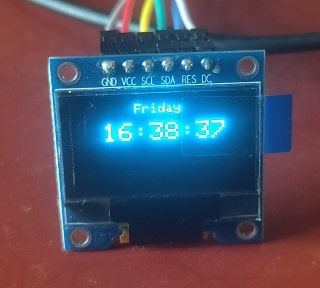
Push button is added for changing cities. This function takes in the parameter &rawtime. FIGURE 1. This is how these digital I/O lines are referred to in the Arduino code. Check the images for further information or watch the video for detailed instructions. The clock doesnt default to DST mode, so the user must push the DST button until the DST string is displayed in the upper right corner of the clock. Whereas in ESP8266 the default I2C pin for SDA is GPIO4 and for SCL is GPIO5. Therefore, this OLED display has improved image quality, full viewing angle, high brightness, better contrast, wide color range, low power consumption, more efficient and reliable as compared to a simple LCD display. udp.read(packetBuffer, NTP_PACKET_SIZE); // Read packet into the buffer
In the past, when it comes to time keeper, we use the RTC (Real Time Clock) chip. The software for the ESP8266 NTP clock was developed using the Arduino IDE. If Wi-Fi goes down but the clock remains powered, the clock will need to be rebooted once the network issue is resolved so NTP time syncing can be restarted. The video above talks you through the entire process of building this project. We will increment the value by 30 each time until the loop reaches 360. packetBuffer[41] << 16;
document.getElementById( "ak_js_1" ).setAttribute( "value", ( new Date() ).getTime() ); You need to adjust the UTC offset for your time zone in milliseconds. if(typeof ez_ad_units != 'undefined'){ez_ad_units.push([[300,250],'iotstarters_com-box-4','ezslot_9',170,'0','0'])};if(typeof __ez_fad_position != 'undefined'){__ez_fad_position('div-gpt-ad-iotstarters_com-box-4-0')}; In order to make the code working, we need a NTP client library. We will display hours, minutes, and seconds individually on the OLED display in the 24 hour HH:MM: SS format. During the day, a sun icon will be displayed in the upper left corner. The OLED displays can vary in size, color, and shape but are primarily programmed in a similar way. Choose the correct board and COM port before uploading your code to the board. This will again be followed by a :. Make sure to select NodeMCU 1.0 (ESP-12E Module) as the board type in the Tools menu. secsSince1900 |= (unsigned long)
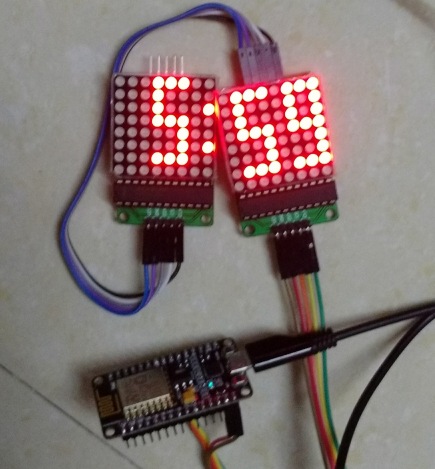
Share it with us! The VCC and GND pins will power the OLED display and will be connected with the ESP boards power supply pins as they require a driving voltage of 3.3-5V. Search for ntpclient and look for NTPClientbyFabrice Weinberg. You can use double-sided tape to hold the OLED module in place and you can also add a bit of hot glue near the wires to keep it in place. esp8266 max7219 clock nodemcu We will need the following components to connect our ESP8266/ESP32 board with the OLED Display. In this tutorial, we will create two types of IoT based clocks such as Analog and Digital using OLED display and ESP32 and ESP8266 NodeMCU development boards. WiFi.hostByName(ntpServerName,
Really nice project to start working on IoT as a beginner. Copyright 2022 T & L Publications. Now, we will define two variables, the GMT offset and the other for the daylight offset in seconds. In order to access the current time we will use the Arduino time library which will help us convert the epoch time to the current time in hour, minute and seconds. But if you want to choose explicitly, use one of the sub-domains pool.ntp.org.
We will program our ESP boards using the Arduino IDE and acquire the current time from the NTP server. Serial.println(No NTP Response);
12e esp8266 nodemcu esp everythingesp adafruit Watch the video for the demonstration below for a better insight. We will use these values to build our analog/digital clocks. #define HOUR_FORMAT_12 true // Set to false for 24 hour time mode, // **********************************************
First, we will set the size of the text using setTextSize() and pass the size as a parameter inside it. The next step is to create the seconds hand of the clock. In our case, it is 0X3C. Next, we will use the configTime() function and pass four arguments inside it. Finally send the data to set up the OLED display. This was tested using the WeMos D1 mini board. Initializes the hardware, logs into the local Wi-Fi network, and then installs the NTP code as the time provider. pool.ntp.org automatically selects time servers that are geographically close to you. The hardware Parts List shows the items required to build one of these NTP clocks and where to get them. I have added switch case statement for selecting cities, by default it will show city 1s time i.e New York. Now, we will set the font size to 2 to display the seconds otherwise the clock wont be properly displayed on the OLED due to its size. We will also require the Adafruit GFX library which is a dependency for SSD1306. Next, we will create two global variables, one for the SSID and the other for the password. Library added successfully, you can see confirmation at the bottom of the Arduino IDE. Manage Your Account - click the "Access" link below to find out more and Log In. If not, make sure you have selected the right time zone for your region. Make the connections according to the table and diagram below. To use the software, unzip it and copy/move the ESP8266NTPClock directory from the zip file into your Arduino directory. // **********************************************. Although there are several types of OLED displays available in the market the one which we will be using is the SSD1306 0.96-inch OLED display. nodemcu esp8266 st7735 // Get a server from the pool
time_t getNTPTime() {, // Try multiple attempts to return the NTP time
They come in just about every conceivable shape and size. While the clock is operational, the time and date will update once a minute. The units of this time stamp are seconds (since 1900) and it is a very large number. We have defined the radius as 35 and will multiply it with the sin(angle) and then add it to 64 for the starting x coordinate. Were currently designing a wide range of products from beginner level kits to industry-standard microcontroller platforms. ESP8266 NTP clock wiring diagram/schematic. We need to adjust the UTC shift for our time zone in milliseconds. We have specified the offsets for Pakistan but you can change them according to your time zone to obtain the correct time. https://github.com/bnbe-club/network-time-using-esp8266-diy-12, https://remotemonitoringsystems.ca/time-zone-abbreviations.php, https://www.youtube.com/channel/UCbWiK1A5RqAugSquBHuyBdA, Arduino Robotic Arm Controlled by Touch Interface.
Then, hit the upload and wait for it to complete. The reason for the popularity is the lower number of pins. The NTPClient library will obatin the epoch time from the time.nist.gov server according to our set GMT offset and daylight savings offset. These are the centre coordinates of the OLED display. Additionally, we will also add a condition for the minute and second. IoT Based Digital World Clock using ESP8266, Circuit Diagram for IoT Based Digital World Clock using ESP8266, Code for IoT Based Digital World Clock using ESP8266 NodeMCU, WebCam Motion Detection With Motioneyeos Using Raspberry Pi, Motion Detection Video Captured Email Alert using Raspberry Pi 4, Raspberry Pi Home Security System Project [Stream Live Video], Arduino Calculator with TFT Touch Screen Display. electronics open The clock mechanisms in PCs work differently.
We will call WiFi.begin() and pass the SSID and password variables inside it which we defined before. These multi-part series may be just what you need! In actuality, I used an ESP8266 variant called a NodeMCU LUA Amica as it has lots of digital I/O pins available, making interfacing to the display trivial. delay(10);
esp8266 We will use the Arduino time.h library to convert the epoch time to the current time and fetch individual hour, minutes and seconds. Once completed, plug in the board and make sure you have selected the right board settings as seen in the image. LCD driver code specific to the Adafruit 1.8 (black tab) display utilizing the hardware SPI interface of the ESP8266. Next, you must set the correct time zone offset for your location. return 0;
Now, by using print() on the display object we will pass timeinfo->tm_sec to display the current second. Whereas the other OLED libraries are the ones which we previously installed and are required for the proper functionality of the OLED display. // 8 bytes of zero for Root Delay & Root Dispersion
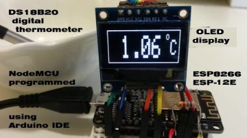
humidity thermometer temperature clock tps esp8266 wifi weather station display The most common job configuration is in client-client mode. Convert this UTC time in millisecond, it will be -4*60*60. In this tutorial, we will see how to make IoT based Digital World Clock using ESP8266. These will be used to create the face of the clock. In IoT projects executing any operations at a specific time or showing the time to the user has always been one of the challenges ahead. The version of these libraries I used to develop the NTP clock is included in the zip file for this article. If you want to use a different LCD display, you will have to find/develop an appropriate driver yourself. esp8266 oled chipskey developement 12f Data is in xbm format. In this tutorial, we will let you know about NTP Digital Clock using ESP8266 and OLED Display.
udp.beginPacket(address, 123); // NTP requests are to port 123
utcOffsetInSeconds is a UTC offset time, You can find your own country or regions UTC offset time. it shows up at the esp.restart(). First and most importantly you must modify the code with the SSID and password of your Wi-Fi network. If you havent setup your Arduino IDE for ESP8266, First of all set up Arduino IDE for ESP8266 and again come back to this project. You can download the code from below link. These clocks listen for WWV radio transmissions from Fort Collins, CO, and synchronize their time keeping mechanisms to the atomic clock reference used for these transmissions. Response);
According to Wikipedia: NTP is a networking protocol for clock synchronization between computer systems over packet-switched, variable-latency data networks. Pressing the DST button again toggles the clock out of DST mode. Next convert this angle to radians and then find the ending coordinates for the line that will represent the second hand. As daylight saving time comes and goes, the user will be required to inform the clock by pressing the DST pushbutton which toggles this mode on and off. esp8266 ntp timezone instructables
This clock has a single pushbutton switch that if configured for daylight saving time operation (more on this later) allows the user to put the clock into and take the clock out of DST mode. The sun icon will be replaced by a moon icon after about 8 p.m. in the evening. First , we will clear the buffer then set the size of the text using setTextSize() and pass the size as a parameter inside it. These will hold our network credentials which will be used to connect to our wireless network. esp8266 clock ntp oled digital display using conclusion If there is no error in the serial monitor then after a few moments, the OLED will start displaying the Digital clock that will update after every second. All user configuration items are found in the ESP8266NTPClock.ino file. It is up to the user to set the clock to the correct time. After you have uploaded your code to the ESP32 or ESP8266 development board, press its ENABLE/RST button. PCs usually sync their RTC using an Internet standard called Network Time Protocol, or NTP. It is a standard Internet Protocol for synchronizing computer clocks with some specific NTP server over network. Now let us proceed towards the digital clock. First, we will create a tm structure called timeinfo that will be set to the localtime() function. Next convert this angle to radians and then find the ending coordinates for the line that will represent the minutes hand. NTP Digital Clock using ESP8266 and OLED Display, NodeMCU based WiFi Network Scanner with OLED Display, IoT Heart Rate Monitoring with ThingSpeak Platform, Temperature Monitoring with ESP-DASH Webserver, Wemos D1 Mini Web Server based Servo Motor Control, ESP8266 Web Server for Controlling Electrical Devices, Smart Switch using Blynk | IoT Based WiFi Switch, PIR based Motion Switch | PIR Sensor Light, IoT based water level Indicator using ESP8266, IoT Vehicle Parking System using ESP8266 and Blynk. Privacy Policy | NTP is a standard internet protocol that is widely used to synchronize computer clocks to a reference network. The first common solution to this challenge is to use RTC modules such as the DS1307, which are usually inaccurate. These are the centre coordinates of the OLED display. Subscribe to our blog to be the first one to view our content. About: #BnBe is a platform to help teach electronics no matter what the age or skill level. FIGURE 3. We learn how to build a cute little digital clock that communicates with NTP servers and displays network or internet time. After calling the libraries, we have to make changes from the following section, which is actually related to the Wi-Fi network used to receive data. Clocks like these typically require the user to select their time zone, but other than that do not offer any controls for manually setting the time. To use the OLED display in our project, we have to install the Adafruit SSD 1306 library and Adafruit GFX library in Arduino IDE. packetBuffer[43]; return secsSince1900 - 2208988800UL +
Main program. esp8266 clock simplest internet local oled instructables Copy the code given below in that file. So lets take a quick look at the code to see how it works. You must modify the following two variables with your network user information so that ESP8266 can communicate with the existing network. Now we have connected the NodeMCU board with OLED display as per the connection diagram and powered on the project. The wire by wire connections are shown in Table 1 (in case theyre not be clear from the Fritzing diagram). First, many ESP8266 modules can be purchased for under $10 in single unit quantities. clock ntp nodemcu esp8266 matrix digital circuit step components required Functions for sending UDP packets to NTP servers, and retrieving the GMT time and converting it to local time. oled clock esp8266 using iot ajax jpralves nodemcu arducam mini web camera If good quality components are used in the clock, time keeping accuracy can be pretty good. Before you can upload the sketch, make sure that you have installed the U8g2 library along with the board support package for the ESP8266 boards. For the Analog clock, we will first build the clock face, hour, minute, and second hands and accordingly acquire the time from the NTP server to display the Analog clock appropriately. One for the Analog clock and the other for the Digital clock. In this project, only two components are used, a nodemcu board with ESP8266 chip and an OLED display with ssd1306 chip. Remember, libraries must be installed in the arduino/libraries directory on your development computer and the Arduino IDE must be restarted to recognize them. 2 years ago. This protocol can be used to synchronize all network devices with synchronized global time (UTC) in a few milliseconds. Let us take a look at the OLED display which we will be using in this article. The ESP8266 NTP clock software is available at the article link; its called Lindley_ESP8266NTPClock.zip. To build this project, you will need a WeMos D1 mini or compatible board that uses the ESP8266 chipset along with an OLED module. FIGURE 4. If you are not sure how to upload the code then you can refer the guides below. esp8266 clock instructables Basing a digital clock design on NTP requires access to the Internet which can be expensive to implement, but allows for a very simple clock design for a couple of reasons. Whereas the hardware for this clock borders on the trivial, the software/firmware for the clock is a bit more involved and complex. This user guide is divided into the following sections: Our aim is to build two types of OLED based clocks: Analog and Digital using ESP32 and ESP8266 boards. If you are using the RESET pin then specify the GPIO through which you are connecting it with your development board. Therefore go to Tools > Board and select ESP32 Dev Module or NodeMCU 1.0. Similarly it goes for all the cities. Go to, Sketches Include Libraries Manage Libraries Search NTPClient Install. If you want to use any GPIO pins for I2C, you will have to set it in code using SoftI2C(). Misc functions for formatting the time data for display on the LCD. Set the cursor as well. Use the wiring diagram above to connect the OLED module to the microcontroller board. }
Initial Wi-Fi connection display. for New York UTC offset time is -4 Hour. See https://tools.ietf.org/html/rfc5905#section-7.3 for an explanation of the fields in the UDP request packet. #define WIFI_PASS xxxxxxxxxxxxx, #define TIMEZONE_OFFSET -7 // Set your timezone offset (-7 is mountain time)
But these chips are not quite accurate, so you have to make manual adjustments over and over again to make them synchronous. The NTP code in the file NTP.h is more complex, however. The first two parameters are the starting coordinates and the next two parameters are the ending coordinates of the line. packetBuffer[12] = 49;
Follow the schematic diagrams below for both the ESP modules and connect them accordingly. Likewise, we will multiply the radius with the cos(angle) then subtract it from 32 to get the starting y coordinate. Set HOUR_FORMAT_12 true to run your clock in 12 hour format; otherwise, it will operate in the 24 hour time format. Then, we will initialize the OLED display by creating an object of Adafruit_SSD1306 and specifying the width, height, I2C instance (&Wire), and -1 as parameters inside it. -1 specifies that the OLED display which we are using does not have a RESET pin. Inside our setup() function, we will initialize the serial communication at a baud rate of 112500. Figure 2 shows the design wired up and working on a breadboard. char daysOfTheWeek[7][4] = {"SUN", "MON", "TUE", "WED", "THU", "FRI", "SAT"}; NTPClient timeClient(ntpUDP, "pool.ntp.org", utcOffsetInSeconds); while ( WiFi.status() != WL_CONNECTED ) {, utcOffsetInSeconds = 5*60*60+60*30; // +5.5 UTC, utcOffsetInSeconds = 10*60*60; // +10 UTC, if (currentMillis - previousMillis >= interval) {. memset(packetBuffer, 0, NTP_PACKET_SIZE); // Initialize values needed to form NTP request
For this project, you dont need RTC Clock Module, Time will be updated from NTP. The getNTPTime function pulls this all together: // NTP Time Provider Code
To overcome the problems with manual time, date setting, and time drift, many so called atomic clocks or radio controlled clocks have appeared on the market. Its name shows that it is a flat light emitting technology that is developed when two organic thin films are connected in series between two electric conductors. We will first acquire the seconds from the tm structure by accessing tm_sec and update it to the floating variable called angle. This will save the time in seconds multiplied by 6. int size = udp.parsePacket();
If you are planning to supply power rather than USB, you need to supply separate 5v for LCD. The starting x and y coordinates of the line will be 64 and 32 respectively.
delay(4000);
Now we will display these same hour, min and second on the OLED display. NTP is intended to synchronize all participating computers to within a few milliseconds of Coordinated Universal Time (UTC). A time stamp packet contains several pieces of information such as date, time, accuracy, latency or time zone. By packetBuffer[0] = 0b11100011; // LI, Version, Mode
By default, the I2C pin in ESP32 for SDA is GPIO21, and for SCL is GPIO22. For detailed information, you can refer to the UTC time list. If clock power is lost, the connection to the Internet will automatically be reestablished once power is restored; the clock will automatically set itself to the correct time. esp8266 #define WIFI_SSID xxxxxxxx
Security Electronics Systems And Circuits, Build a Farmer, Fox, Chicken, Corn Puzzle, Vintage Tek: Continuously Variable Autotransformers, Restoration of a Vintage Zenith G725 AM/FM Receiver, Build a Digital Clock Family Using Nextion Displays. Serial.print(daysOfTheWeek[timeClient.getDay()]); //Serial.println(timeClient.getFormattedTime()); lcd.print(daysOfTheWeek[timeClient.getDay()]); , Copy this code and upload it to arduino. Enter your email address to subscribe to this blog and receive notifications of new posts by email. Installing ESP8266 library in Arduino IDE. You will however require a steady internet connection for this project. Built-in low power 32-bit CPU which can double as an application processor, Standby power consumption of less than 1.0 mW (DTIM3). NTP can work in several ways. Additionally, you also need to install the ESP32 and the ESP8266 plugin. You will get projects on Arduino, Raspberry pi & NodeMcu ESP8266. This corrected value is used by the Time library, and converted to the current time and date displayed by this clock. esp8266 clock simplest internet local oled instructables After the connection is made, the ESP board will send a request to the server. The next step is to draw the clock face. The ground of both the devices will be held common. The basic premise is that a client device such as ESP8266 connects to the server using User Datagram Protocol (UDP) on port 123. realTimeZoneOffset * SECS_PER_HOUR;
We will acquire the hour from the tm structure by accessing tm_hour. The OLED performs faster in SPI communication but it is popular with I2C communication. Two things to take into account while accessing the time for your time zone is to look for the Coordinated Universal Time (UTC) offset and the daylight savings offset. The ESP8266 NTP clock breadboard. Figure 3 shows the clocks display while a connection is being made to the local Wi-Fi network. See the file Misc.h for the EEPROM read/write code. Our ESP development board will be the client and will connect to a time server using the NTPClient library.
Plugin the microUSB cable and it should work as expected. Serial.println(Transmitted NTP Request);
pool.ntp.org is an open NTP server suitable for such cases. Hi, I made your project and it is indeed well designed. // Set all bytes in the buffer to 0
Push button is added for changing cities. This function takes in the parameter &rawtime. FIGURE 1. This is how these digital I/O lines are referred to in the Arduino code. Check the images for further information or watch the video for detailed instructions. The clock doesnt default to DST mode, so the user must push the DST button until the DST string is displayed in the upper right corner of the clock. Whereas in ESP8266 the default I2C pin for SDA is GPIO4 and for SCL is GPIO5. Therefore, this OLED display has improved image quality, full viewing angle, high brightness, better contrast, wide color range, low power consumption, more efficient and reliable as compared to a simple LCD display. udp.read(packetBuffer, NTP_PACKET_SIZE); // Read packet into the buffer
In the past, when it comes to time keeper, we use the RTC (Real Time Clock) chip. The software for the ESP8266 NTP clock was developed using the Arduino IDE. If Wi-Fi goes down but the clock remains powered, the clock will need to be rebooted once the network issue is resolved so NTP time syncing can be restarted. The video above talks you through the entire process of building this project. We will increment the value by 30 each time until the loop reaches 360. packetBuffer[41] << 16;
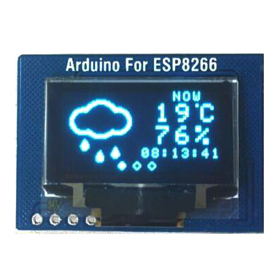
document.getElementById( "ak_js_1" ).setAttribute( "value", ( new Date() ).getTime() ); You need to adjust the UTC offset for your time zone in milliseconds. if(typeof ez_ad_units != 'undefined'){ez_ad_units.push([[300,250],'iotstarters_com-box-4','ezslot_9',170,'0','0'])};if(typeof __ez_fad_position != 'undefined'){__ez_fad_position('div-gpt-ad-iotstarters_com-box-4-0')}; In order to make the code working, we need a NTP client library. We will display hours, minutes, and seconds individually on the OLED display in the 24 hour HH:MM: SS format. During the day, a sun icon will be displayed in the upper left corner. The OLED displays can vary in size, color, and shape but are primarily programmed in a similar way. Choose the correct board and COM port before uploading your code to the board. This will again be followed by a :. Make sure to select NodeMCU 1.0 (ESP-12E Module) as the board type in the Tools menu. secsSince1900 |= (unsigned long)
Share it with us! The VCC and GND pins will power the OLED display and will be connected with the ESP boards power supply pins as they require a driving voltage of 3.3-5V. Search for ntpclient and look for NTPClientbyFabrice Weinberg. You can use double-sided tape to hold the OLED module in place and you can also add a bit of hot glue near the wires to keep it in place. esp8266 max7219 clock nodemcu We will need the following components to connect our ESP8266/ESP32 board with the OLED Display. In this tutorial, we will create two types of IoT based clocks such as Analog and Digital using OLED display and ESP32 and ESP8266 NodeMCU development boards. WiFi.hostByName(ntpServerName,
Really nice project to start working on IoT as a beginner. Copyright 2022 T & L Publications. Now, we will define two variables, the GMT offset and the other for the daylight offset in seconds. In order to access the current time we will use the Arduino time library which will help us convert the epoch time to the current time in hour, minute and seconds. But if you want to choose explicitly, use one of the sub-domains pool.ntp.org.
We will program our ESP boards using the Arduino IDE and acquire the current time from the NTP server. Serial.println(No NTP Response);
12e esp8266 nodemcu esp everythingesp adafruit Watch the video for the demonstration below for a better insight. We will use these values to build our analog/digital clocks. #define HOUR_FORMAT_12 true // Set to false for 24 hour time mode, // **********************************************
First, we will set the size of the text using setTextSize() and pass the size as a parameter inside it. The next step is to create the seconds hand of the clock. In our case, it is 0X3C. Next, we will use the configTime() function and pass four arguments inside it. Finally send the data to set up the OLED display. This was tested using the WeMos D1 mini board. Initializes the hardware, logs into the local Wi-Fi network, and then installs the NTP code as the time provider. pool.ntp.org automatically selects time servers that are geographically close to you. The hardware Parts List shows the items required to build one of these NTP clocks and where to get them. I have added switch case statement for selecting cities, by default it will show city 1s time i.e New York. Now, we will set the font size to 2 to display the seconds otherwise the clock wont be properly displayed on the OLED due to its size. We will also require the Adafruit GFX library which is a dependency for SSD1306. Next, we will create two global variables, one for the SSID and the other for the password. Library added successfully, you can see confirmation at the bottom of the Arduino IDE. Manage Your Account - click the "Access" link below to find out more and Log In. If not, make sure you have selected the right time zone for your region. Make the connections according to the table and diagram below. To use the software, unzip it and copy/move the ESP8266NTPClock directory from the zip file into your Arduino directory. // **********************************************. Although there are several types of OLED displays available in the market the one which we will be using is the SSD1306 0.96-inch OLED display. nodemcu esp8266 st7735 // Get a server from the pool
time_t getNTPTime() {, // Try multiple attempts to return the NTP time
They come in just about every conceivable shape and size. While the clock is operational, the time and date will update once a minute. The units of this time stamp are seconds (since 1900) and it is a very large number. We have defined the radius as 35 and will multiply it with the sin(angle) and then add it to 64 for the starting x coordinate. Were currently designing a wide range of products from beginner level kits to industry-standard microcontroller platforms. ESP8266 NTP clock wiring diagram/schematic. We need to adjust the UTC shift for our time zone in milliseconds. We have specified the offsets for Pakistan but you can change them according to your time zone to obtain the correct time. https://github.com/bnbe-club/network-time-using-esp8266-diy-12, https://remotemonitoringsystems.ca/time-zone-abbreviations.php, https://www.youtube.com/channel/UCbWiK1A5RqAugSquBHuyBdA, Arduino Robotic Arm Controlled by Touch Interface.
Then, hit the upload and wait for it to complete. The reason for the popularity is the lower number of pins. The NTPClient library will obatin the epoch time from the time.nist.gov server according to our set GMT offset and daylight savings offset. These are the centre coordinates of the OLED display. Additionally, we will also add a condition for the minute and second. IoT Based Digital World Clock using ESP8266, Circuit Diagram for IoT Based Digital World Clock using ESP8266, Code for IoT Based Digital World Clock using ESP8266 NodeMCU, WebCam Motion Detection With Motioneyeos Using Raspberry Pi, Motion Detection Video Captured Email Alert using Raspberry Pi 4, Raspberry Pi Home Security System Project [Stream Live Video], Arduino Calculator with TFT Touch Screen Display. electronics open The clock mechanisms in PCs work differently.
We will call WiFi.begin() and pass the SSID and password variables inside it which we defined before. These multi-part series may be just what you need! In actuality, I used an ESP8266 variant called a NodeMCU LUA Amica as it has lots of digital I/O pins available, making interfacing to the display trivial. delay(10);
esp8266 We will use the Arduino time.h library to convert the epoch time to the current time and fetch individual hour, minutes and seconds. Once completed, plug in the board and make sure you have selected the right board settings as seen in the image. LCD driver code specific to the Adafruit 1.8 (black tab) display utilizing the hardware SPI interface of the ESP8266. Next, you must set the correct time zone offset for your location. return 0;
Now, by using print() on the display object we will pass timeinfo->tm_sec to display the current second. Whereas the other OLED libraries are the ones which we previously installed and are required for the proper functionality of the OLED display. // 8 bytes of zero for Root Delay & Root Dispersion
humidity thermometer temperature clock tps esp8266 wifi weather station display The most common job configuration is in client-client mode. Convert this UTC time in millisecond, it will be -4*60*60. In this tutorial, we will see how to make IoT based Digital World Clock using ESP8266. These will be used to create the face of the clock. In IoT projects executing any operations at a specific time or showing the time to the user has always been one of the challenges ahead. The version of these libraries I used to develop the NTP clock is included in the zip file for this article. If you want to use a different LCD display, you will have to find/develop an appropriate driver yourself. esp8266 oled chipskey developement 12f Data is in xbm format. In this tutorial, we will let you know about NTP Digital Clock using ESP8266 and OLED Display.